ATTACHING TO A STRUCTURE
WALL ATTACHMENT
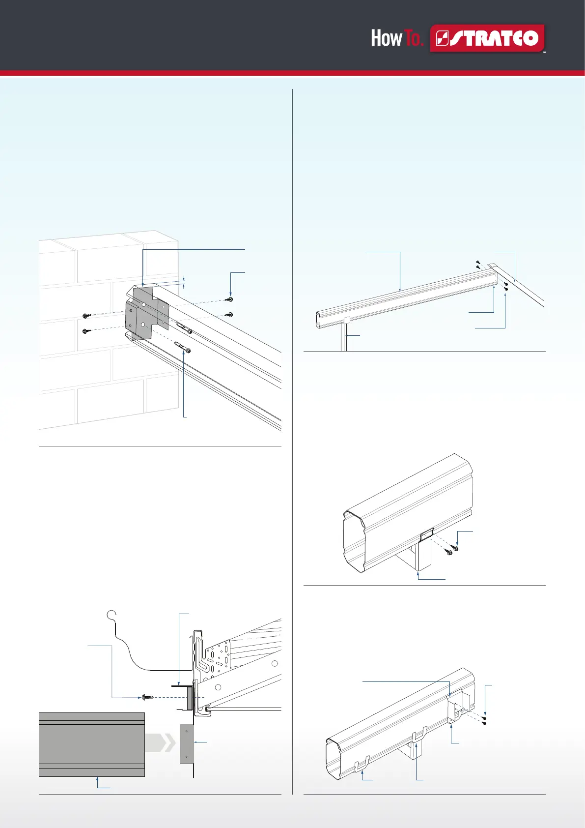
For units attached to a wall, position the wall brackets where
the beams meet the wall. The folded section on the tabs of
the bracket is located at the top. The highest point of the
wall bracket will be 15mm below the top beam. Mark the
holes and drill using an 8mm masonry bit. Fasten the bracket
to the wall with two M8 masonry anchors to a minimum
65mm embedment. The beam is slid into position and
fastened with four 12x20 self drilling screws (Figure 2.0).
SUSPENSION BRACKET ATTACHMENT
A suspension bracket is used when a beam is suspended
from the fascia. The top tab of the bracket must be located
under and over the back channel. Use silicone to seal
behind the suspension bracket and fascia. For steel fascia a
minimum of three 12x20 hex head screws are fixed through
the back channel, suspension bracket and fascia (Figure
2.1). For timber, three 12x25 type 17 screws are used to fix
through the back channel, suspension bracket and timber.
The rafter is slid into position and fastened using four 12x20
self drilling screws (Figure 2.1).
FRAMEWORK ERECTION
END FASCIA BEAM
When installing all beams, ensure the double thickness of
the beam is on top. Install the end fascia beam furthest from
the downpipe first. Lift the back channel end of the beam
up into the wall or suspension bracket while supporting
the other end on an adjustable construction prop. Adjust
the construction prop to allow for the required deck fall
minimum of one degree (or one and a half degrees for deck
spans over 4000mm). Fasten the end fascia beam to the
bracket using two 12x20 hex head screws either side in the
holes provided (Figure 3.0).
BRACKET AND FILLER CONNECTIONS
Measure the front fascia beam. Mark where the end fascia
beams, intermediate beams (if required) and columns meet.
Clip the post brackets onto the bottom of the front fascia beam
where the columns will sit. Fasten through the holes in the post
bracket with two 10x25 countersunk screws each side into the
flute of the beam (Figure 3.1).
Place the beam brackets on the inside face of the front fascia
beam, aligning their curved flange with the top groove of the
beam so that they clamp the beam fillers (notched beam filler
if over a post bracket) in place, fasten using two 12x20 self
drilling screws (Figure 3.2).
Two M8 masonry anchors,
or two 8mm diameter
screwbolts with a minimum
embedment of 65mm
Two 12 x 20
self-drilling
screws on
each side
15mm
Wall Bracket
FIGURE 2.0
Back Channel
Three 12 x 20mm
Self Drilling Screws
or
Three 12 x 25mm Timber
Fixing Screws (Timber
Fascia) through Back
Channel and Suspension
Bracket
Suspension Bracket
Rafter
FIGURE 2.1
End Rafter
Two 12x20 Self Drilling
Screws either side of the
Suspension Bracket
Construction Prop
Back Channel
Suspension Bracket
FIGURE 3.0
Post Bracket
Fasten with two
10x25 countersunk
screws per side
FIGURE 3.1
Beam Filler
Curved
Flange
Notched Beam Filler
Over Post Bracket
Beam Bracket
Clamps Over
Beam Filler
Two 12x20 hex
head screws
FIGURE 3.2
 Loading...