21 MA_560_A4_180619_en
3.6.2
Class 560-11 only
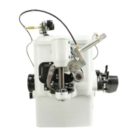
Mounting and setting the plunger drive
(Fig. 11, Fig. 13, Fig. 14 and Fig. 15)
ATTENTION!
Switch off machine electrically!
With repair or replacement, e.g. of the swivel drive, the plunger drive must be
newly mounted and set. Please heed the following instructions:
1. Swivel drive (1) must be aligned in its secured state so that the shaft of
the swivel drive, looking from the back, is turned to the limit in the
clockwise direction.
2. Insert and screw in the connection flange (2) to the limit so that the first
threaded hole is over the groove and fix with the threaded pin with journal
(3) and secure with nut (4). (Fig. 13)
3. Mount shaft (5) and secure to the surface with the 2 threaded pins (6).
Then tighten the last threaded pin (7) and secure the rest of the nuts (4).
(Fig. 13)
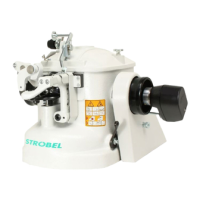
4. Setting lever (4) on shaft (5) (Fig. 14):
a. Lightly clamp the lever on the shaft.
b. Turn the regulating bolt (1) in the thread on the lower arm. Push on
gearwheel (2) and regulating knob (3) and secure provisionally; pay
attention to the surface of the regulating bolt (1). (Fig. 14)
c. Set the gearwheel (3) to the dimension 2.6 mm. (Fig. 11)
d. Turn the regulating bolt (1) back using the regulating knob (3) until
gearwheel (2) rests against the cast eye. (Fig. 14)
e. Bring the swivel drive to the limit, press lever (4) to the crest of the
regulating bolt (1), tighten the lever (4) and bore with shaft 130.0460
(5). (Fig. 14)
5. Screwing regulating bolt (1) until by means of lever (4) it has moved the
magnet approx. 0.2 mm back from its limit stop. (Fig. 14)
6. Loosen the gear (2), push it back to the limit Stop on the boss and tighten
it well. (Fig. 14)
7. Screwin the regulating bolt further 2 ¾ turns (distance from gear and boss
approx. 2 mm), press regulating knob (4) to the limit Stop (lower arm) and
tighten it well. The plunger adjustment is limited by the limit stops of gear
and regulating bolt at the lower arm. (Fig. 11)