Page 8 of 14
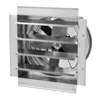
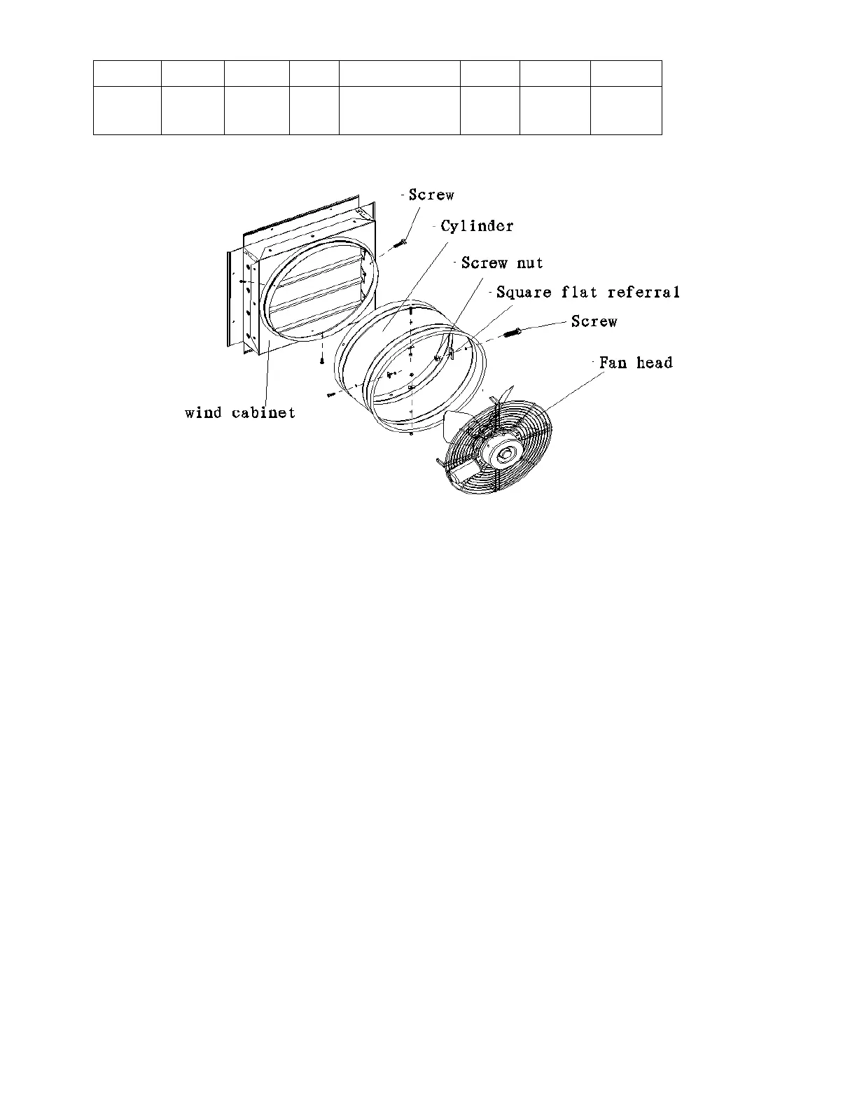
1. Use screws, nuts, and flat referrals to assemble the fan head to the shutter assembly and then firmly
fasten the nuts and flat referrals to lock into place.
Important: Use appropriate screws for framework and wall conditions.
2. To mount the shutter assembly, use the eight pre-punched 1/4" x 1/2" slotted mounting holes of the
shutter assembly to attach the unit to the framework.
3. Attach the fan to the installation wall surface as follows for applicable wall structure.
Wood Structure - Use 1/4’’ lag screws of appropriate length through each mounting hole.
Steel Structure - Use 1/4’’bolt of appropriate length for application, in combination with a 1/4’’flat
washer and a 1/4’’nut.
Masonry Structure - Use 1/4’’ lag screws in combination with a lag shield or equivalent 1/4’’ masonry
fastener of appropriate length.
Note: The above mentioned hardware for mounting fans to wall surfaces is not provided by the
manufacturer since each mounting application is different. However these items can be obtained from
your local hardware store.
4. This unit is not equipped with a speed control switch, only a single exhaust air volume. Use the
appropriate connection mode to connect the power supply. All connections in the junction box are
connected to the power supply (see wiring diagram).
 Loading...