AA
FF
GG
NN
AA
FF
GG
NN
1
7
ASSEMBLY INSTRUCTIONS
GG
GG
AA
FF
FF
O2
AA
A
A
O2
O1
Wrench
Hardware Used
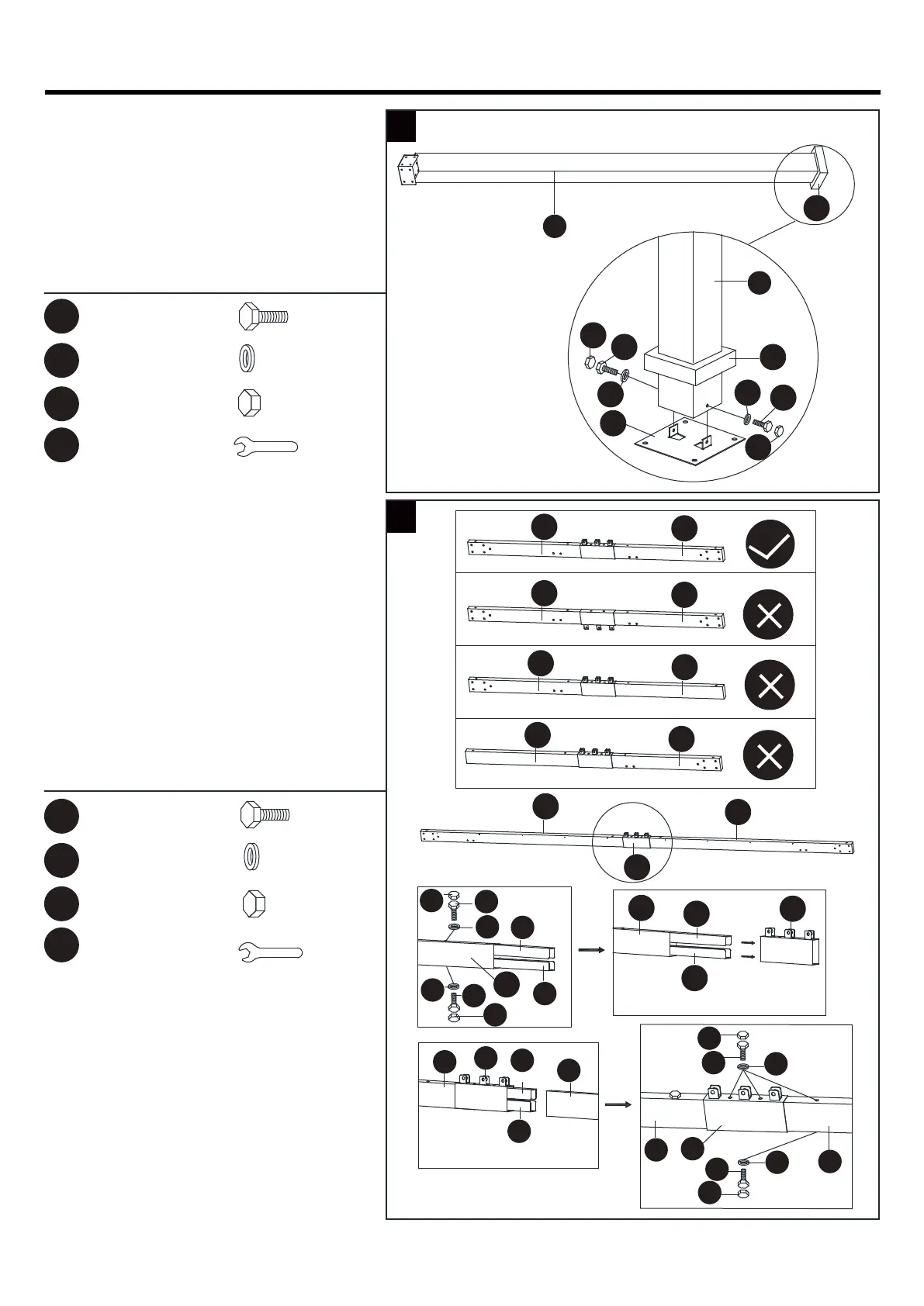
1. Slide the Base Cover (O2) over the
bottom of the Post (A) and connect
the Base (O1) to the Post (A) with
Bolt (AA) plus Flat Washer (FF).
Add Bolt Cover (GG). Repeat for all
four posts.
2. Insert the Beam Connector (I) into
the Right Beam (C2) and add the
Decorative Cover (K). Then connect
the Left Beam (C1), attach with Bolt
(AA) plus Flat Washer (FF). Add Bolt
Cover (GG). Repeat for all four sides.
NOTE: Pls do not install the screws
under the Decorative Cover (K) in
this step.
Bolt Cover
X24
X24
X24
X1
Flat Washer
X8
X8
X8
X1
M6 x 15 mm Bolt
Wrench
Bolt Cover
Flat Washer
M6 x 15 mm Bolt
Hardware Used
2
C2
C2
K
I
I
I
C2
C1
K
I
I
GG
FF
C1
C2
K
AA
GG
FF
AA
C2
GG
AA
FF
FF
AA
GG
I
C1
K
I
C1
C2
C2
C1
C2
C1
C1
C2


 To Next Page