ABS-31
ABS (DIAGNOSTICS)
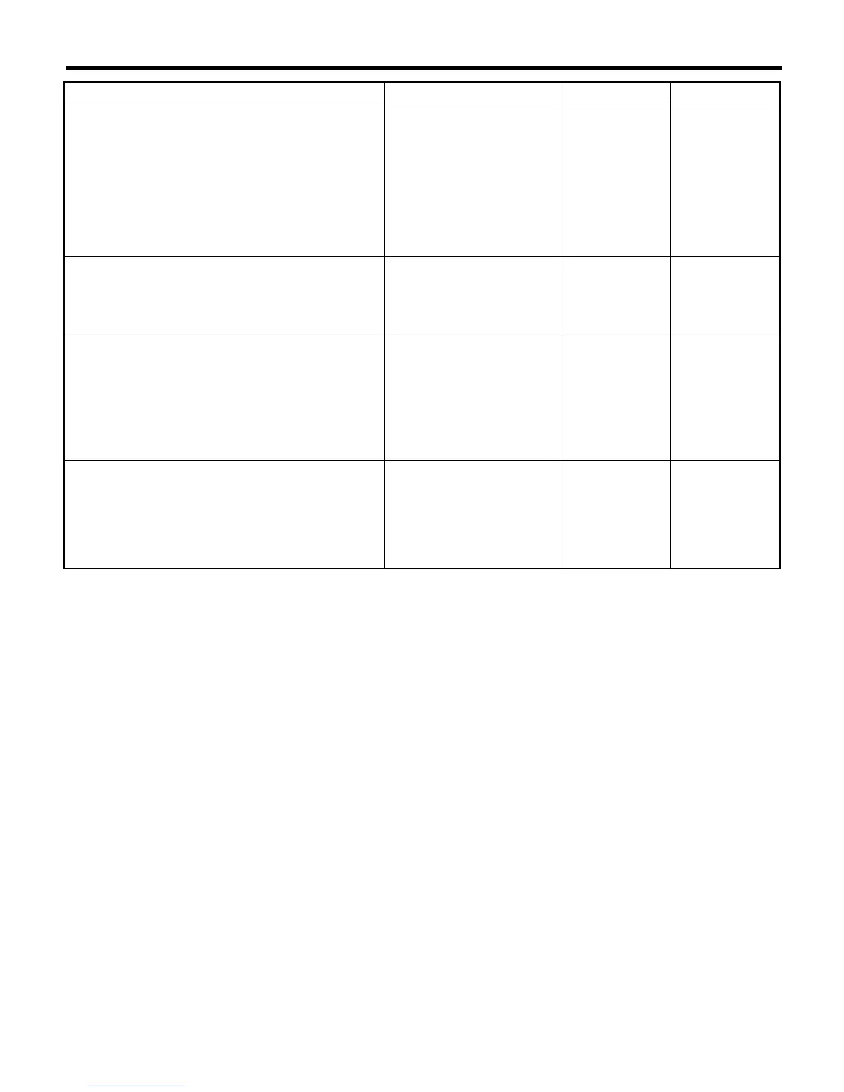
DIAGNOSTICS CHART WITH DIAGNOSIS CONNECTOR
7 CHECK BATTERY SHORT OF ABS WARN-
ING LIGHT HARNESS.
1)Turn ignition switch to ON.
2)Measure voltage between connector (F74)
and chassis ground.
Connector & terminal
LHD: (F74) No. 19 (+) — Chassis ground
(
−
−−
−
):
RHD: (F74) No .20 (+) — Chassis ground
(
−
−−
−
):
Is the voltage less than 3 V? Go to step
8.
Repair wiring har-
ness.
8 CHECK GROUND CIRCUIT OF ABSCM&H/U.
Measure resistance between ABSCM&H/U
and chassis ground.
Connector & terminal
(F49) No. 23 — GND:
Is the resistance less than 0.5
Ω
?
Go to step
9.
Repair
ABSCM&H/U
ground harness.
9 CHECK WIRING HARNESS.
Measure resistance between connector (F74)
and chassis ground.
Connector & terminal
LHD: (F74) No. 19 (+) — Chassis ground
(
−
−−
−
):
RHD: (F74) No .20 (+) — Chassis ground
(
−
−−
−
):
Is the resistance less than 0.5
Ω
?
Go to step
10.
Repair harness/
connector.
10 CHECK POOR CONTACT IN CONNECTORS.
Turn ignition switch to OFF.
Is there poor contact in con-
nectors between combination
meter and ABSCM&H/U?
Repair connector. Replace
ABSCM&H/U.
<Ref. to ABS-7,
ABS Control Mod-
ule and Hydraulic
Control Unit
(ABSCM&H/U).>
Step Check Yes No
 Loading...