ABS-45
ABS (DIAGNOSTICS)
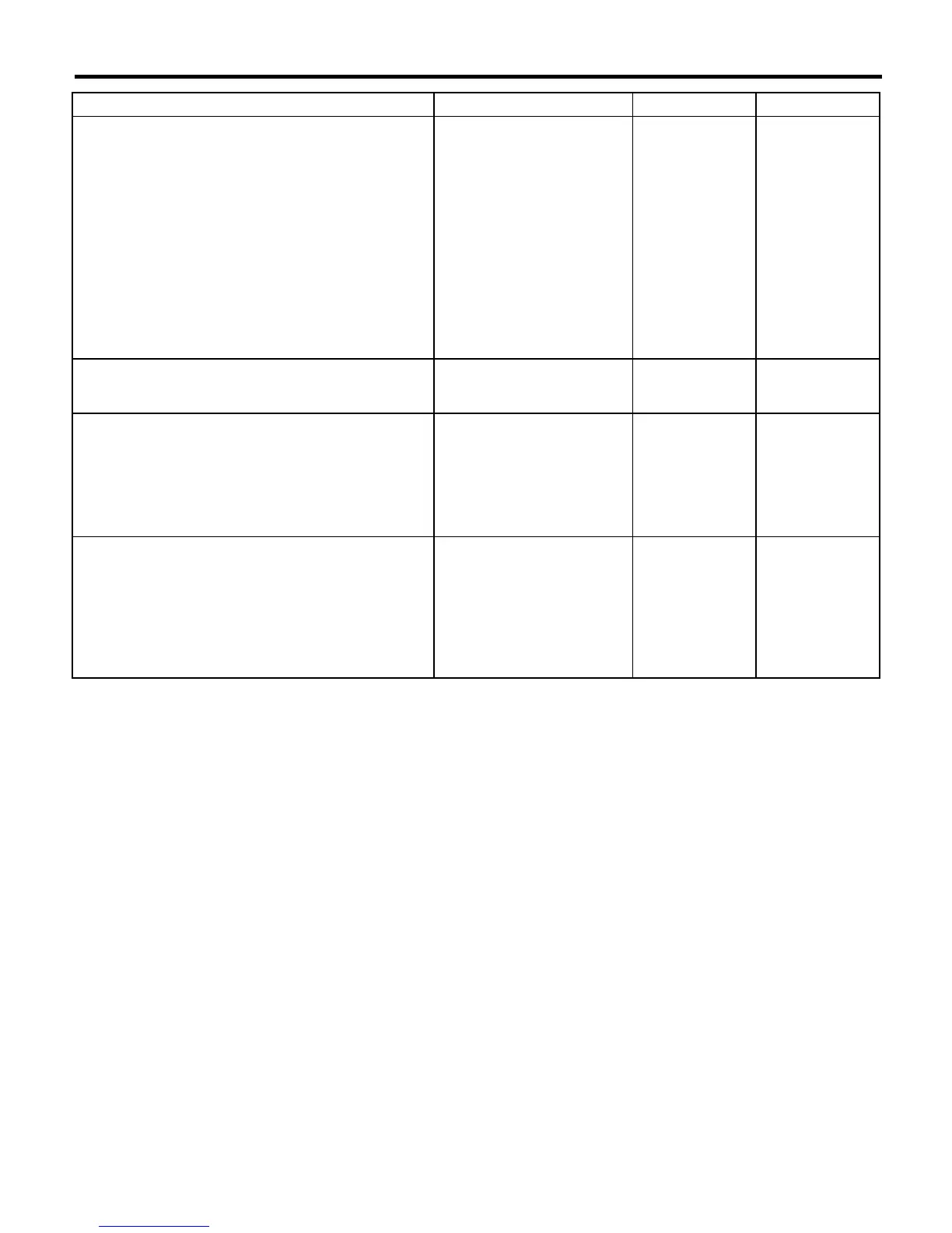
DIAGNOSTICS CHART WITH DIAGNOSIS CONNECTOR
11 CHECK GROUND SHORT OF HARNESS.
1)Turn ignition switch to OFF.
2)Connect connector to ABS sensor.
3)Measure resistance between ABSCM&H/U
connector terminal and chassis ground.
Connector & terminal
Trouble code 21 / (F49) No. 11 — Chassis
ground:
Trouble code 23 / (F49) No. 9 — Chassis
ground:
Trouble code 25 / (F49) No. 14 — Chassis
ground:
Trouble code 27 / (F49) No. 7 — Chassis
ground:
Is the resistance more than 1
M
Ω
?
Go to step
12.
Repair harness
between
ABSCM&H/U and
ABS sensor.
Replace
ABSCM&H/U.
<Ref. to ABS-7,
ABS Control Mod-
ule and Hydraulic
Control Unit
(ABSCM&H/U).>
12 CHECK POOR CONTACT IN CONNECTORS.
Is there poor contact in con-
nectors between ABSCM&H/U
and ABS sensor?
Repair connector. Go to step
13.
13 CHECK ABSCM&H/U.
1)Connect all connectors.
2)Erase the memory.
3)Perform inspection mode.
4)Read out the trouble code.
Is the same trouble code as in
the current diagnosis still being
output?
Replace
ABSCM&H/U.
<Ref. to ABS-7,
ABS Control Mod-
ule and Hydraulic
Control Unit
(ABSCM&H/U).>
Go to step
14.
14 CHECK ANY OTHER TROUBLE CODES AP-
PEARANCE.
Are other trouble codes being
output?
Proceed with the
diagnosis corre-
sponding to the
trouble code.
A temporary poor
contact.
NOTE:
Check harness
and connectors
between AB-
SCM&H/U and
ABS sensor.
Step Check Yes No
 Loading...