VDC-29
VDC (DIAGNOSTICS)
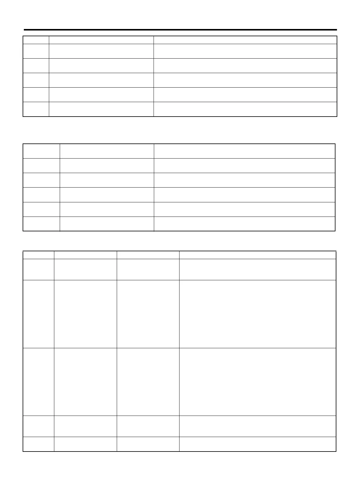
LIST OF DIAGNOSTIC TROUBLE CODE (DTC)
If any of the following multiple diagnostic trouble codes (DTCs) are present in memory, check the area cor-
responding to the first diagnostic trouble code (DTC). If no problem is detected, check the areas correspond-
ing to the other diagnostic trouble codes (DTCs) in order of their appearance.
2. WITH SUBARU SELECT MONITOR
52 Abnormal motor and/or motor relay
<Ref. to VDC-108, DTC 52 ABNORMAL MOTOR AND/OR MOTOR
RELAY, Diagnostics Chart with Diagnosis Connector.>
71 Abnormal steering angle sensor
<Ref. to VDC-114, DTC 71 ABNORMAL STEERING ANGLE SENSOR,
Diagnostics Chart with Diagnosis Connector.>
72 Abnormal yaw rate sensor
<Ref. to VDC-118, DTC 72 ABNORMAL YAW RATE SENSOR, Diagnos-
tics Chart with Diagnosis Connector.>
73 Abnormal lateral G sensor
<Ref. to VDC-122, DTC 73 ABNORMAL LATERAL G SENSOR, Diagnos-
tics Chart with Diagnosis Connector.>
74 Abnormal pressure sensor
<Ref. to VDC-126, DTC 74 ABNORMAL PRESSURE SENSOR, Diagnos-
tics Chart with Diagnosis Connector.>
Combination
of DTC No.
Problem area Index No.
46, 74
(F87) — No. 78, 68 or 69 lead circuit
is shorted to ground or battery.
<Ref. to VDC-86, DTC 46 ABNORMAL VOLTAGE OF 5 V POWER SUP-
PLY, Diagnostics Chart with Diagnosis Connector.>
44, 71
(F87) — No. 83 or 81 lead circuit is
open.
<Ref. to VDC-114, DTC 71 ABNORMAL STEERING ANGLE SENSOR,
Diagnostics Chart with Diagnosis Connector.>
51, 48, 71 (F87) — No. 27 lead circuit is open.
<Ref. to VDC-114, DTC 71 ABNORMAL STEERING ANGLE SENSOR,
Diagnostics Chart with Diagnosis Connector.>
71, 51, 44 (F87) — No. 27 lead circuit is open.
<Ref. to VDC-114, DTC 71 ABNORMAL STEERING ANGLE SENSOR,
Diagnostics Chart with Diagnosis Connector.>
72, 73 (F87) — No. 63 lead circuit is open.
<Ref. to VDC-122, DTC 73 ABNORMAL LATERAL G SENSOR, Diagnos-
tics Chart with Diagnosis Connector.>
DTC No. Display screen Contents of diagnosis Index No.
—
Communication for ini-
tializing impossible
Select monitor commu-
nication failure
<Ref. to VDC-130, COMMUNICATION FOR INITIALIZING
IMPOSSIBLE (SELECT MONITOR COMMUNICATION FAIL-
URE), Diagnostics Chart with Select Monitor.>
— No trouble code
Although no diagnostic
trouble code appears
on the select monitor
display, the ABS warn-
ing light and/or VDC
warning light and/or
VDC operating indicator
light and/or VDC OFF
indicator light remains
on.
<Ref. to VDC-33, Diagnostics Chart with Diagnosis Connec-
tor.>
— No trouble code
Although no diagnostic
trouble code appears
on the select monitor
display, the ABS warn-
ing light and/or VDC
warning light and/or
VDC operating indicator
light and/or VDC OFF
indicator light remains
off.
<Ref. to VDC-33, Diagnostics Chart with Diagnosis Connec-
tor.>
21
Front right ABS sensor
circuit open or shorted
battery
Open or short circuit in
front right ABS sensor
circuit
<Ref. to VDC-133, DTC 21 FRONT RIGHT ABS SENSOR CIR-
CUIT OPEN OR SHORTED BATTERY, Diagnostics Chart with
Select Monitor.>
22
Front right ABS sensor
signal
Front right ABS sensor
abnormal signal
<Ref. to VDC-139, DTC 22 FRONT RIGHT ABS SENSOR SIG-
NAL, Diagnostics Chart with Select Monitor.>
DTC No. Contents of diagnosis Index No.


 To Next Page
 Loading...