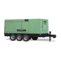
Figure 2-4: Compressor Flow Diagram - All Models
1. Compressor Air FIlter 11. Fluid Cooler
2. Engine Air FIlter 12. Thermal Valve/Fluid Filter Assembly
3. Engine 13. Receiver Tank
4. Compressor Unit 14. Fluid Level Sight Gauge
5. Service Air (Aftercooled) 15. Final Fluid Separator Element
6. Discharge Air Filters 16. Ball Valve
7. Air Inlet Valve 17. P3 Pressure Transducer
8. Moisture Separator 18. Service Air (Non-Aftercooled)
9. Aftercooler 19. Minimum Pressure Check Valve
10. Relief Valve 20. Temperature Shutdown Switch

 Loading...