67
375 John Deere Standard and Aftercooled/Filtered Operator’s Manual and Parts List
MAINTENANCE
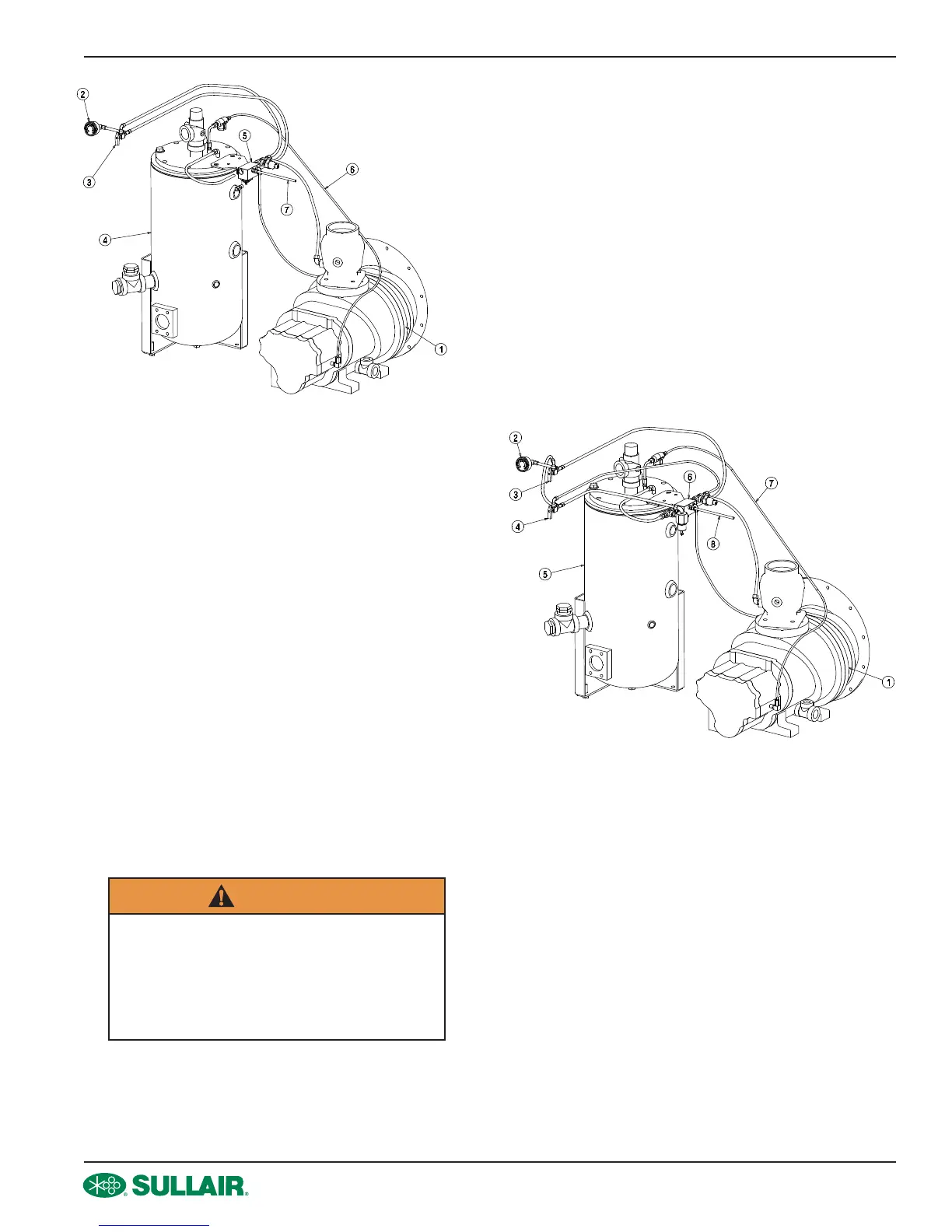
Compressor Unit1.
Air Pressure Gauge2.
Warm-Up Control Valve3.
Receiver Tank4.
Pressure Regulator/Blowdown Manifold5.
Oil Return Line6.
Blowdown Line (To Fitting At Filter Hose)7.
Figure 5-4: Control System Adjustment –
Standard Pressure
The following procedure applies to a compressor with full-
load pressure rating of 100 psig (6.9 bar).
Remove the speed control module (mounted on lifting 1.
bail) mounting screws and lift the module away from
the mounting surface. Turn the module over to expose
the engine speed adjustment buttons.
Start the compressor and allow the engine to warm- 2.
up to its normal operating temperature with the service
valve closed.
With service valve closed, set the engine low speed 3.
(idle) to it’s specied setting with the LO (+) or LO (-)
buttons on the speed control module. Holding the LO
(+) button will increase the idle speed: holding the LO
(-) butting decreases the idle speed setting.
Adjust the pressure regulator setting to maintain 115 4.
psig (8 bar) receiver tank pressure.
Gradually open the service valve to atmosphere until 5.
the engine speed increases and the receiver tank
pressure stabilizes at 100 psig (6.9 bar). Adjust the
engine high idle speed to its specied setting with the
HI (+) or HI (-) buttons on the speed control module.
Holding the HI (+) button will increase the high idle
speed: holding the HI (-) butting decreases the high
idle speed setting.
Open the service valve to 100 psig (6.9) (rated full- 6.
load pressure) and recheck maximum engine speed
and control response. Close the service valve and
allow the compressor to cycle and recheck the low
engine idle speed.
To reset the speed control module to the default 7.
values, press the LO (+) and LO (-) buttons at the
same time.
Compressor Unit1.
Air Pressure Gauge2.
Warm-Up Control Valve3.
High/Low Pressure Valve4.
Receiver/Sump Tank5.
Pressure Regulator/Blowdown Manifold6.
Oil Return Line7.
Blowdown Line (To Fitting At Filter Hose)8.
Figure 5-5: Control System Adjustment –
Dual Pressure
WARNING
Operating the compressor at below
its minimum specied idle speed will
damage the compressor. Operating
the compressor in this condition will
cause coupling and/or compressor
failure.
g_5-4std-press-t3-r01
g_5-4a-hi-press-t3-r01

 Loading...


