SECTION 3 4500P-7500 USER MANUAL
33
A1: ALTERNATE INCOMING POWER SUPPLY LOCATION Ø 2.50 [63.5]
A2: SPACE REQUIRED TO OPEN DOORS TYP. SEE NOTE #6
A3: SPACE REQUIRED TO OPEN STARTER PANEL
A4: CONTROLLER
A5: E-STOP
A6: OIL LEVEL SIGHTGLASS
A7: AIR INLET
A8: EXHAUST AIR OUT 2,845 CFM
A9: CONTAINMENT PAN DRAIN
A10: INCOMING CUSTOMER POWER SUPPLY Ø 3.0 (76.2)
A11: MOISTURE DRAIN CONNECTION 1/4"-18 NPT
A12: AIR OUT CONNECTION 2"-11 1/2 NPT
A13: COOLING WATER OUT 1 1/2"-11 1/2 NPT
A14: COOLING WATER OUT 1 1/2"-11 1/2 NPT
NOTES:
1. Allow 4.00 feet [1.25 meters] minimum clearance around machine for access and free circulation of air.
2. A foundation or mounting capable of supporting the weight of package, and rigid enough to maintain the compressor frame
level is required.
3. All dimensions are ± .50" [12.7mm]
4. Recommended incoming customer power supply is shown on drawing.
5. If ductwork is to be installed for cooling air high static fan must be selected. max allowable additional static pressure 0.75 in h o
with high static fan.
6. Doors are removable using lift-off hinge pins.
7. All dimensions shown in inches with millimeter dimensions in parentheses.
ADD 35.3# (16.0 KG) FOR WEIGHT OF WEATHERHOOD
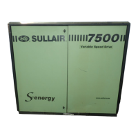
Figure 3-5 Identification - 4500P, 5500 and 7500 Water-Cooled with Weatherhood (continued)

 Loading...