Section 3
13
DMD MODULAR REGENERATIVE DRYER
INSTALLATION
3.1 ESSENTIAL INFORMATION
Care must be taken to ensure that the dryer is not
subject to flows (even peaks) in excess of the dryers
rated capacity, e.g. dryers downstream of an air
receiver have increased potential to be overflowed.
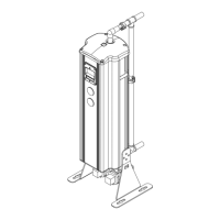
The dryer can be installed free standing, secured to
the floor via the fastening points provided in the base
or secured to a wall using optional brackets.
The dryer must be installed vertical and level.
Suitable rated pipe and connections must be used for
the installation. All pipework must be secure and
safely positioned.
The purge flow is factory set for 100 psig inlet
pressure operation. Should the minimum pressure
requirement be different, the purge flow must be
reset by a Sullair engineer or a Sullair approved
agent.
Ensure the dryer is electrically connected to a supply
suitable for the unit. See wiring diagram printed in
2.3 Electrical Details.
1. Filtration
A 0.01 micron coalescer and a 1 micron par-
ticle after filter is to be installed before and
after the DMD dryer. Filters must be main-
tained by Sullair or a Sullair approved agent.
2. By-pass Line
A by-pass line ensures complete safety
during maintenance and enables a continu-
ous supply of compressed air to be main-
tained if required. It should be remembered
that air bypassing the dryer is dirty untreated
air.
3.2 TECHNICAL SPECIFICATION
Table 3-1: Operating Specification
Parameter Minimum Maximum Nominal
Inlet Pressure 60 psi g (4.1 bar g) 230 psi g (16.0 bar g) 100 psi g (6.9 bar g)
Inlet Temperature 40°F (4.4°C) 120°F (48.9°C) 95°F (35°C)
Table 3-2: Electrical Specification
Dryer Model Voltage Supply Supply Need Electrical Approval
50-60 Hz 80-240V 1 phase CE/CSA/UL
 Loading...