4: Installation ShopTek™ ST4, ST5, ST7, ST11, ST15 Three-phase 60 Hz User Manual
88292018-236 R00
36 Subject to EAR, ECCN EAR99 and related export control restrictions.
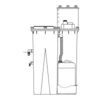
4.3 Service air piping
Before installing the compressor, review the service air
system’s layout including: pipe sizes, auxiliary separator
tube, drip legs, line filter(s), and isolation valves (see Fig-
ure 4-3 on
page 36).
Figure 4-3: Typical service air piping
1. Sullair compressor 5. Standard gate valve
2. Sullair dryer 6. By-pass gate valve
3. Shut-off gate valve A1. Condensate drain
4. Sullair filter A2. Air outlets
NOTE
Systems using both reciprocating and rotary
screw compressors must isolate the two types
from each other through the use of a common
receiver tank. Air lines from each individual com-
pressor should be connected directly to the com-
mon receiver tank.
 Loading...