Section 2
ShopTek™ ST4, ST5, ST7, ST11, ST15 Three-phase 60 Hz User Manual 2: Description
88292018-236 R00
Subject to EAR, ECCN EAR99 and related export control restrictions. 9
Description
2.1 Introduction
The design of the Sullair ShopTek line of compressor
units is a single stage, positive displacement, flooded
rotary screw. A complete package includes the:
• Compressor unit
•
Electric motor
•Starter
• Compressor inlet and discharge systems
• Compressor lubrication and cooling system
• Controller
• Aftercooler (ST11 and ST15 only)
• Heavy gauge steel mounting frame
New compressors are shipped from the factory fully
charged with
Sullube
®
lubrication fluid. Section 3.2 and
Section 3.3 describe lubrication requirements and recom-
mendations for each c
ompressor package.
External piping, connectors, an
d the enclosure should be
inspected and maintained in accordance with the proce-
dures and recommendations in this manual.
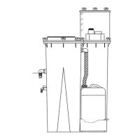
2.2 Compressor component
description
The ShopTek compressor (Figure 2-1 and Figure 2-2)
uses a fan to draw outside air into the enclosure, cooling
the
motors, the combined radiator fluid cooler, and air
aftercooler. This hot air is then vented out of the top of
the enclosure.
Fluid is injected into the compressor, and mixes directly
with
the air as the rotors turn which compresses the air.
The fluid flow has three basic functions:
• As a coolant, it controls the air temperature rise
no
rmally associated with the heat of compres-
sion.
• Seals the clearance paths between the rotors
and the stator, and also between the two rotors.
• Provides a lubricating film between the rotors
allowing one rotor to directly drive the other,
which is an idler, and also lubricates the bearings.
After the air/fluid mixture is discharged from the compres-
sor unit, the fluid is separated from the air. At this time,
the
air flows through an aftercooler and separator, and
then to the service line while the fluid is cooled and fil-
tered in preparation for reinjec
tion.
CAUTION
Use only one type of a recommended compres-
sor lubricant. Adding a different one, or mixing
lubricants can cause damage and/or malfunc-
tions, and will void the compressor’s warranty.
NOTE
The compressor air end requires no internal
inspections or maintenance actions. Opening
the compressor air end’s housing may void its
warranty. (This does not apply to the shaft seal
or inlet valve which are replaceable.)
 Loading...