Output Section Controls:
14. Output variable resistor controls overall output signal level; this is a post-
preamp and post-compressor gain control preceding the 990 discrete solid
state output
note: this feature enables the user to saturate both the preamp
tube and the compressor tube while still maintaining a proper signal level
sending to other devices - i.e. recording media
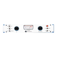
15. Level/G.R. 2 position switch selects the VU meter's mode of operation;
in level mode, the meter indicates peak amplitude of output signal; in G.R.
mode, the meter indicates the gain reduction is being applied to the signal
note: this meters right to left from 0 VU
16. Link/In/Bypass 3 position switch selects stereo linked compression, compression
engaged, or bypass compressor (preamp by itself)
note: when linking two MPC-100A's for stereo operation, the unit
which is set for the most compression will act as the controller for both
units; also, a 1/4" mono connection is required between units
Back Panel Connections:
Mic Input female XLR jack for microphone signal in
Line Input female XLR jack for line level signal in (Pin 3 is + of balanced pair)
Side Chain 1/4" stereo jack for balanced signal in for ducking and d'essing
Stereo Link 1/4" mono jack to connect two MPC-100A's for stereo compression
-10 dB Output 1/4" mono jack for low level -10 dB unbalanced signal out
+4 dB Output male XLR jack for pro level +4 dB balanced signal out (Pin 3 is hot)