Do you have a question about the sunair GSB-900 and is the answer not in the manual?
Overview of the manual's content and purpose.
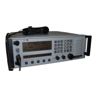
Detailed description of the GSB-900 transceiver's components.
Explanation of the front panel controls and indicators.
Description of the optional control panel interface.
Details on the receiver and exciter module's function.
Explanation of the synthesizer module's operation.
Description of the filter module's role in frequency selection.
Overview of the power supply module and its functions.
Comprehensive technical data, operating parameters, and performance characteristics.
Detailed receiver performance specifications.
Specifications related to the transmitter's power output.
List of items included with the GSB-900 transceiver.
Main unit and power supply details.
Specifications of the included microphone.
Details of the included documentation.
Power cord specifications for different voltage inputs.
Description of the ancillary kit.
Details of the TCXO component.
List of accessories and spare parts available separately.
Information on the remote antenna coupler.
Information on the automatic antenna coupler.
Details on the linear power amplifier.
General guidelines and considerations for installing the transceiver.
Procedures for safely unpacking and inspecting the equipment.
Instructions for preparing the unit for reshipment.
Comprehensive information on mounting and general installation practices.
Detailed instructions for setting up a base station.
Procedures for installing the transceiver in a vehicle.
Specifics for marine base station installations.
Guidelines for mounting the unit in a standard 19-inch rack.
Essential information regarding antenna types and grounding.
Details on narrow band antenna types and their installation.
Information on random length antennas.
Discussion of broad band antenna requirements.
Details on power sources and operating conditions.
Considerations for high line voltage operation.
Procedures for operating from DC power sources.
Final checks to ensure correct installation.
General operational overview and important notes.
Detailed explanation of all front panel controls and their functions.
Information on rear panel fuses and connector locations.
Procedures for operating the transceiver with a 50 ohm antenna.
Steps to prepare for antenna operation.
Detailed operating procedures for 50 ohm antennas.
Instructions for using the antenna coupler.
Operation of the automatic antenna tuner controls.
Details on the operation of the KW control unit.
Explanation of the overall functional block diagram.
Detailed theory of the synthesizer module.
Theory behind the spectrum generator.
Theory of the mixer and frequency counter circuits.
Theory of the voltage controlled oscillator (VCO).
Theory of the translator module.
Theory of VFO and 21 MHz reference amplifiers.
Theory of the VFO buffer.
General theory of the VHF divider.
Theory of the preset counters.
Theory of the VFO module.
General theory of receiver electronics.
Theory of the VHF mixer board.
Theory of the RF amplifier stage.
Theory of the sideband generator board.
Theory of the IF/Filter board.
Theory of the RF power amplifier.
Theory of the 12VDC and 5VDC regulators.
Theory of the filter module.
Theory of the RF detector board.
Theory of the voltage ALC detector.
Theory of the DC relay control circuit.
Theory of the key line interface.
Theory of the receiver filter board.
Theory of the motor control board.
General principles for maintenance and repair.
Procedures for routine preventive maintenance.
Instructions for removing the equipment covers.
Procedures and equipment for performance testing.
List of required test equipment.
Preliminary steps for performance testing.
Procedures for testing and aligning the synthesizer.
Troubleshooting guide for synthesizer faults.
Testing and alignment of synthesizer subassemblies.
Alignment procedures for the receiver/exciter board.
Alignment steps for the VFO board.
Procedure for VFO sweep alignment.
Alignment steps for the receiver board.
Testing and verification of the 10 kHz switch.
Testing and verification of the 1 kHz switch.
Testing and verification of the 100 Hz switch.
Testing the IHF VFO coarse steering.
Testing the VHF VFO coarse steering.
Alignment procedures for synthesizer dial functions.
Testing the DC voltage generator.
Testing the 1 MHz DC voltage generator.
Testing the 1 kHz DC voltage generator.
Testing the 10 kHz DC voltage generator.
Testing the 13.75 MHz DC voltage generator.
Testing the 21 MHz DC voltage generator.
Testing the 13.75 MHz frequency generator.
Testing the 21 MHz frequency generator.
Testing the translator module.
Testing and aligning the VFO sweep.
Testing the 10 kHz DC voltage generator.
Testing the 100 kHz DC voltage generator.
Testing the 1 kHz DC voltage generator.
Testing the 10 kHz frequency generator.
Testing the 100 kHz frequency generator.
Testing the 1 kHz frequency generator.
Testing and aligning the VFO sweep.
Testing the VFO voltage generator.
Procedures for removing major modules from the unit.
Steps to remove the filter module.
Servicing and removal of the front panel.
Steps to remove the power supply module.
Procedures for removing and servicing the RF power amplifier.
Guidelines for repairing and maintaining PCBs.
Explanations of common logic gates and devices.
Reference to the schematic diagrams for detailed circuit analysis.
Information regarding the phone patch accessory.
Instructions for installing the phone patch unit.
Operating procedures for the phone patch.
Details about the receiver protector module.
Instructions for installing the receiver protector.
Information about the optional blower kit.
Details for the GRC-951 remote control unit.
Theory of operation for the GRC-951.
Installation procedures for the GRC-951.
Operation procedures for the GRC-951.
Troubleshooting guide for the GRC-951 unit.
| Brand | sunair |
|---|---|
| Model | GSB-900 |
| Category | Transceiver |
| Language | English |