L2
L1
CT
CT
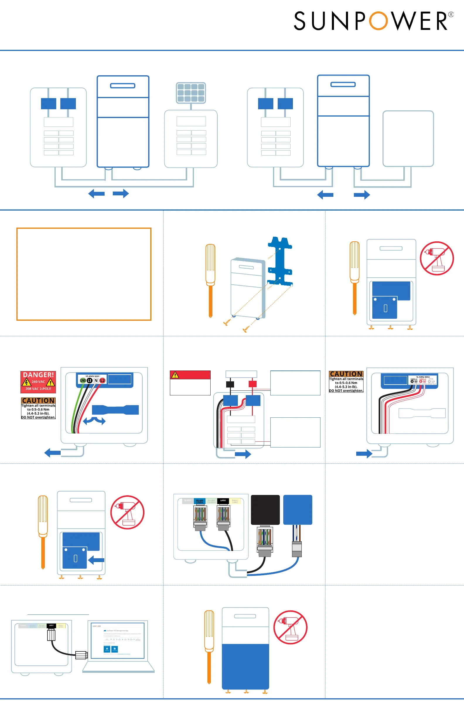
2. Remove all PVS5x covers
1. Mount the PVS5x
3. Wire PVS5x power
4. Install consumption CTs
Refer to Section 3 on the other side for complete CT installation instructions.
6. Replace PVS5x wiring covers
5. Wire consumption CTs
7. Connect DC inverter communication
Never run
communication cable and
AC wiring in same conduit
SMA US-40
Inverter
SMA US-22
Inverter
2
7
5
o 0 g B b G br BR
T-568B
RJ-45 Plug
Clip is pointed
away from you
o 0 g B b G br BR
T-568B
RJ-45 Plug
Clip is pointed
away from you
D+ D- GND
B b BR
o 0 g B b G br BR
T-568B
RJ-45 Plug
Clip is pointed
away from you
10. Replace PVS5x cover
8. Connect PVS5x to the internet
Customer’s Wi-Fi
Ethernet Cable
PLC Adapter
(optional SunPower accessory)
9. Commission with PVS Management App
https://www.sunpowerconsole.com
PVS5x Quick Start Guide
Refer to the PVS5x Installation
Instructions on the other side for the complete PVS5x installation instructions.
SUNPOWER
CT
CT
Main Service Panel
PVS5x Connection Diagram: DC Inverter Site
\
DC Inverter
PVS5X
Wire PVS5x power and CTs
into main service panel
Wire communication
from PVS5x to inverter
SUNPOWER
Wire PVS5x into AC
module subpanel
Wire CTs into main
service panel
AC Module Subpanel
CT
CT
Main Service Panel
PVS5x Connection Diagram: AC Module Site
AC Module Array
PVS5X
From CTs around
service conductors
Load-Side System:
downstream of CTs
Line-Side System:
upstream of CTs
To PVS5x
To 15 A or 20 A
dual-pole breaker
Routing wire and cable:
• Fill all openings in the enclosure with
components rated Type 4 or better to
maintain the integrity of the enclosure’s
environmental system
•
do not
•
•
•
Note:
Place lower cover
over AC power wires
Hazardous voltage
DANGER!
AC WIRING PARTITION
AC WIRING PARTITION
 Loading...