Do you have a question about the Sunrise Medical Rhapsody and is the answer not in the manual?
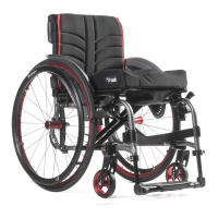
| Type | Manual Wheelchair |
|---|---|
| Wheel Size | 24 inches |
| Seat Depth | 16 inches |
| Backrest Height | 16 inches |
| Frame Material | Aluminum |
| Armrest Style | Optional, various styles available |
| Footrest Style | Swing-away |
| Weight Capacity | 125 kg (275 lbs) |
LEDs indicating charge level.
On/Off, Horn, Speed/Profile controls.
LEDs displaying speed and profile settings.
Wiring details for motor connections.
Wiring details for charger connections.
Pin assignments for the VR2 controller.
Recommended tools for service tasks.
Electrical schematic of the controller package.
Procedure for resetting the circuit breaker.
Steps to test voltage at the joystick.
Method to check battery voltage and condition.
Diagnosing issues when the chair is not charging.
Verifying voltage at the battery connection points.
Inspecting the battery wire harness for polarity and voltage.
Testing the battery fuse for continuity.
Measuring resistance across the circuit breaker.
Replacing the main wiring harness if issues persist.
Interpreting speed indicator patterns like ripples and flashes.
Understanding various battery gauge LED patterns and their meanings.
Interpreting the one-bar diagnostic code for low battery.
Diagnosing the two-bar code for a disconnected left motor.
Troubleshooting the three-bar code for left motor wiring faults.
Diagnosing the four-bar code for a disconnected right motor.
Troubleshooting the five-bar code for right motor wiring faults.
Understanding the six-bar code indicating charger connection.
Diagnosing the seven-bar code for joystick issues.
Interpreting the eight-bar code for control system faults.
Diagnosing the nine-bar code for solenoid brake faults.
Troubleshooting the ten-bar code for excessive battery voltage.
Resolving communication errors indicated by seven bars and speed profile.
Step-by-step instructions for removing the seat assembly.
Procedures for adjusting and removing the footrest.
Steps for removing the top and front shrouds.
Instructions for safely removing the batteries.
Steps to remove the main control module.
Procedure for removing the left and right motors.
Steps for removing and reinstalling suspension shocks.
Procedure for removing and replacing caster wheels.
Steps for removing the onboard charger unit.
How to adjust the ride stiffness via the suspension nut.