Need help?
www.sunseisolar.com
+1 514.270.5770
Operating Instructions
Register your warranty online and enter to win an ICP Solar product. www.icpsolar.com/warranty
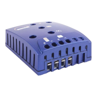
CHARGECONTROLLER CC25000
LOADS: System loads such as lights, radios and DC/AC
inverters must be 12V or 24V DC (unless an inverter is being
used).
INSTALLATION
WARNING: Electricity, even low voltage electricity, can be
dangerous. Installation should be performed by a licensed
electrical contractor or other qualifi ed personnel only.
The requirements of National Electrical Codes should be
followed.
WARNING: Follow all safety precautions of the battery
manufacturer. Proper ventilation must be provided for the
batteries. Most batteries produce hydrogen gas when
charging, which is extremely explosive. Provide adequate
battery ventilation. DO NOT expose the battery to open fl ame,
matches, cigarettes or sparks.
CAUTION: DO NOT EXCEED THE UNIT’S VOLTAGE AND
CURRENT RATINGS
Do not exceed the maximum open circuit voltage (Voc) rating
of 30V for 12V operating systems or 50V for 24V operating
systems. This is the sum of the Voc of all solar panels in
series.
Do not exceed the maximum current rating 25A. This is the
sum of the peak operating current (Ip) of all the solar panels
in parallel.
Do not deviate from the recommended wiring instructions.
INFORMATION
> The charge controller SHOULD NOT BE USED in direct
> sunlight or temperatures exceeding 122ºF (50ºC) or below
> -40ºF (-40ºC). It should be installed within 5 feet (1.5m)
> of the battery in a cool, dry and well ventilated area.
> Intended for indoor use.
> DO NOT USE MORE THAN 25A (400W for 12V or 800W
> for 24V) of solar power with the Sunsei™ CC25000.
> ALL connections should be in PARALLEL (Positive to
> Positive, Negative to Negative). Ensure that connections
> are clean and solid.
> Always CONNECT the BATTERY FIRST, and
> DISCONNECT
the BATTERY LAST. It is recommended
> connecting a fuse close to the battery on wires extending
> from it, especially for longer runs. Follow electrical codes
> where applicable.
> For all additions or longer distances, use up to #6
> (gauge) wires. Always CONNECT the BATTERY FIRST,
> and DISCONNECT the BATTERY LAST.
PROCEDURE
Mount charger on a dry non-fl ammable surface. Use mounting
holes.
1. CONTROLLER TO BATTERY CONNECTION: Connect
positive and negative wires into designated positive and
negative terminals of the controller. Then carefully connect
wires to battery and/or fuse terminal (see wire selection table
below).
2. CONNECT PANELS: If connecting more than one solar
panel, connect the solar panels to the master cable in parallel,
+ to + and - to -.
3. CONTROLLER TO PANEL CONNECTION: Connect positive
and negative master cable wires to designated positive and
negative terminals of the charge controller.
4. WIRE TYPE: When possible, use stranded wire instead of
solid wire. Stranded wire does not fatigue and cause loose
connections over time as easily as solid wire. Use red wire for
(+) and black for (-).
5. WIRE SIZE: Refer to the “WIRE GAUGE” charts below to
determine the minimum size wire needed for each connection.
Note that the bigger the wire, the lower the AWG. When using
large stranded wire, you may need to divide the ends into two
groups and straddle the screw on the terminal block.
RECOMMENDED WIRE GAUGE CHARTS
6. COMPLETE THE INSTALLATION OF PANELS, BATTERY
AND LOAD
LOCATION
The Sunsei
TM
CC25000 should be mounted where it can be
easily seen and reached as needed. Carefully consider how
the wires are to be run from the solar panel to the controller
and from the controller to the battery. The Sunsei
TM
CC25000
should be mounted as close to the battery as possible to
reduce voltage drop in the wires. Wires extending from the
battery should be fused. Respect local electrical codes where
applicable.
Recommended Wire Gauge (AWG) Chart to limit voltage drop to 0.5V
Panel to Charge Controller
Cable Length (ft.)
0 to 10
10 to 20
20 to 30
30 to 40
40 to 50
50 to 60
SE-1200
14
14
14
14
14
12
SE-4000
14
14
12
12
10
10
SE-6000
14
12
10
10
8
8
SE-8000
14
12
10
8
8
6
Cable Length (ft.)
0 to 5
5 to 10
10 to 15
15 to 20
SE-1200
14
14
14
14
SE-4000
14
14
14
12
SE-6000
14
14
12
10
SE-8000
14
12
10
8
Recommended Wire Gauge (AWG) Chart to limit voltage drop to 0.3V
Charge Controller to Battery
 Loading...