Form 43343320
-50- Aug 2012
IGNITION MODULE DIAGNOSTICS
IGNITION MODULE DIAGNOSTICSIGNITION MODULE DIAGNOSTICS
IGNITION MODULE DIAGNOSTICS
Flame Fault
Flame FaultFlame Fault
Flame Fault
If at any time the main valve fails to close completely and maintains a flame, the full time flame sense circuit
will detect it and energize the combustion blower. Should the main valve later close completely removing the
flame signal, the combustion blower will power off following the post purge period.
Fault Conditions
Fault ConditionsFault Conditions
Fault Conditions
MULTIPURPOSE METER
USE
MICROAMP
SCALE
BLACK (-)
RED (+)
LED Display
GND
V2
FC-
FC+
V1
(W)TH
Ignition Module (Fenwal)
Flame Sensor Current Check
(R) 24VAC
L1
IND
NC
P.SW
S1
Error Mode
Error ModeError Mode
Error Mode
LED Indication
LED IndicationLED Indication
LED Indication
Internal Control Failure
Internal Control FailureInternal Control Failure
Internal Control Failure
Steady On
Steady OnSteady On
Steady On
Air Flow Fault
Air Flow FaultAir Flow Fault
Air Flow Fault
1 Flash
1 Flash1 Flash
1 Flash
Gas valve failure (stuck open)
Gas valve failure (stuck open)Gas valve failure (stuck open)
Gas valve failure (stuck open)
2 Flashes
2 Flashes2 Flashes
2 Flashes
Ignition Lockout
Ignition LockoutIgnition Lockout
Ignition Lockout
3 Flashes
3 Flashes3 Flashes
3 Flashes
The LED located on the ignition module will flash ON
for ¼ second, then OFF for ¼ second during a fault
condition. The pause between fault codes is 3
seconds.
24.0) INSTALLATION DATA
Installation:
System:
No.
Model:
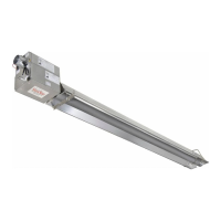
SPS
SPSSPS
SPS
or
or or
or SPU
SPUSPU
SPU
L = Propane Gas
 Loading...


