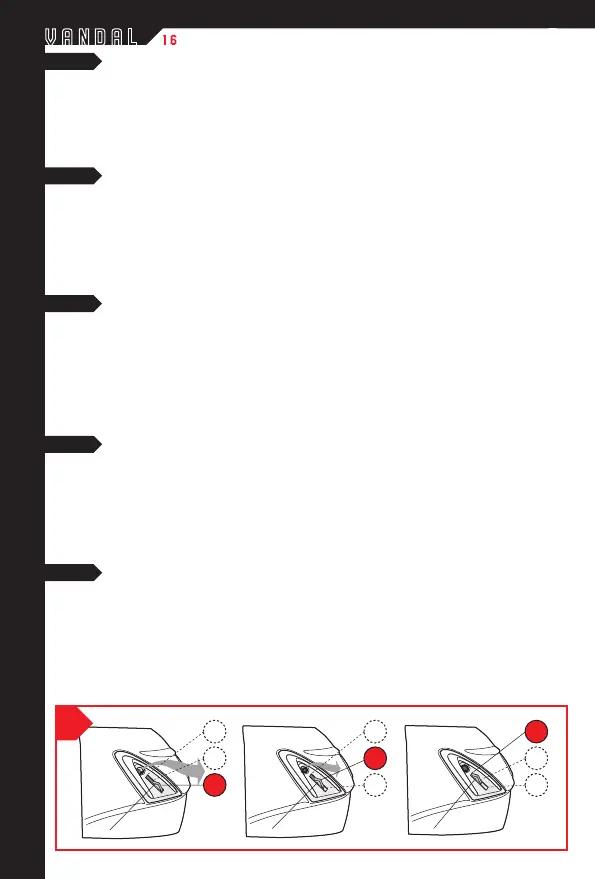
REAR AIR VENT - OPERATION - see figure 6
The airflow in the upper part of the helmet can by adjusted by means of the slider (A) located on both the rear air vents:
- position (1): move slider (A) to the rear of the helmet as far as it will go > air vent completely open
- position (2): move slider (A) to the central position > air vent partially open
- position (3): move slider (A) to the front of the helmet > air vent completely closed.
The slider will click into place in each of the three positions when moving it to and from.
PRISES D’AIR ARRIERE - FONCTIONNEMENT - voir figure 6
Le flux d’air qui pénètre dans la partie supérieure du casque peut être réglé en agissant sur le curseur (A) situé sur les
deux prises d’air arrièfre:
- position (1): curseur (A) amené vers la partie arrière du casque jusqu’à la position d’arrêt > prise d’air complètement ouverte
- position (2): curseur (A) amené en position intermédiaire > prise d’air partiellement ouverte
- position (3): curseur (A) amené vers la partie avant du casque > prise d’air complètement fermée.
Les trois positions sont reconnaissables à un léger déclic qui se fait entendre durant le déplacement du curseur.
PRESE D’ARIA POSTERIORI - FUNZIONAMENTO - vedi figura 6
Il flusso di aria nella parte superiore del casco può essere regolato agendo sul cursore (A) presente su entrambe la prese
aria posteriori:
- posizione (1): cursore (A) spostato verso la parte posteriore del casco fino alla posizione di fermo > presa d’aria
completamente aperta
- posizione (2): cursore (A) collocato in posizione intermedia > presa d’aria parzialmente aperta
- posizione (3): cursore (A) spostato verso la parte frontale del casco > presa d’aria completamente chiusa.
Le tre posizioni sono avvertibili da un leggero scatto durante lo spostamento del cursore.
HINTERE LÜFTUNGSÖFFNUNGEN - FUNKTIONSWEISE - siehe Abbildung 6
Die im oberen Helmbereich einströmende Luft kann anhand des Schiebereglers (A) auf beiden hinteren Lüftungsöffnungen
reguliert werden:
- Stellung (1): Schieberegler (A) am hinteren Anschlag des Helms > Lü'9fftungsöffnung vollständig offen
- Stellung (2): Schieberegler (A) in Zwischenposition > Lüftungsöffnung teilweise offen
- Stellung (3): Schieberegler (A) in Richtung des frontseitigen Helmbereich > Lüftungsöffnung vollständig geschlossen.
Wenn die drei Stellungen jeweils erreicht werden, ist ein leichtes Klicken beim Verschieben des Reglers zu vernehmen.
TOMAS DE AIRE POSTERIORES - FUNCIONAMIENTO - vea figura 6
El flujo de aire en la parte superior del casco puede regularse actuando en el cursor (A) presente en ambas tomas de aire
posteriores:
- posición (1): cursor (A) desplazado hacia la parte posterior del casco hasta la posición de tope > toma de aire
completamente abierta
- posición (2): cursor (A) colocado en posición intermedia > toma de aire parcialmente abierta
- posición (3): cursor (A) desplazado hacia la parte frontal del casco > oma de aire completamente cerrada.
Las tres posiciones son perceptibles por un suave clic durante el desplazamiento del cursor.
2
3
A
1
2
3
6
E
INSTRUCCIONES DE USO
D
GEBRAUCHSANLEITUNGEN
I
ISTRUZIONI D’USO
F
MODE D’EMPLOI
G
USER’S INSTRUCTIONS
1
2
3
A
A
1
 Loading...