Sutron Corporation 8310 & 7310 Users Manual 8800-1125Rev. 2.7 (BETA) 4/16/2014 pg. 28
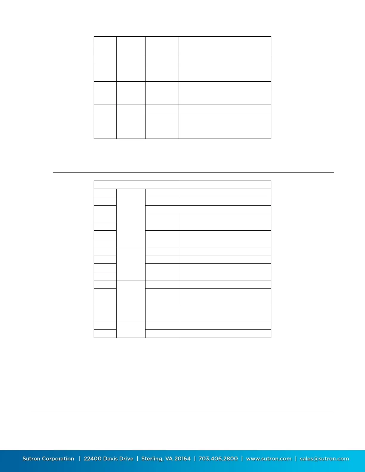
Protected 12 (protected with self-
resetting fuse, 900 mA max)
Switched 12 (battery / protected
with self-resetting fuse, 900 mA max)
Protected 5V (system voltage with
self resetting fuse, 300mA max)
Switched 5V (system voltage
protected with self-resetting fuse and
solid state switch, 500 mA max)
D – Digital Inputs, Outputs, COM4, Modem
Idles High (Standard RS-485
nomenclature this would be B)
Idles Low (Standard RS-485
nomenclature this would be A)
Note: The 8310 provides a very weak bias to maintain the RS-485 idle condition. If the
connecting device is expecting stronger bus biasing, then external biasing resistors can be
added: one resistor between the D14 (RS485B) and GND terminals with a second resistor
between D13 (RS485A) and PROT +5V terminals. For mild biasing, use 100K resistors. For much
stronger biasing, use 10K resistors.
SD Card Socket
The SD card socket is located on the front panel of the 8310-N and the left side of the 8310-O.
An LED next to the SD card indicates lights when the SD card is being read or written to.
 Loading...