Do you have a question about the Suzhou Kunteng Electronics Co KT-LCD5 and is the answer not in the manual?
Details the physical dimensions and appearance of the KT-LCD5 meter.
Specifies the primary material (PC) and housing color (dark gray) of the meter.
Illustrates the electrical connections required for the KT-LCD5 meter.
Provides step-by-step guidance on mounting and connecting the meter to the eBike.
Shows a visual representation of the meter installed on the eBike handlebars.
Introduces the various functions and displays offered by the KT-LCD5 meter.
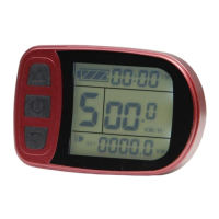
Details the various information displayed on the meter screen.
Explains the standard operating procedures and power management of the meter.
Details how to power the meter on and off, including auto-shutdown.
Describes the primary display mode upon meter startup.
Explains how the battery level is visually represented on the display.
Details how the single trip time (TM) is shown on the display.
Shows how the power-assist level (gear) is displayed and selected.
Explains the display of current riding speed in Km/H.
Illustrates how the distance for a single trip (DST) is displayed.
Details the display for the 6Km/h push-assist function.
Shows the indicator for the meter's backlight and vehicle headlights.
Indicates when the brake system is engaged.
Shows when the cruise control function is active.
Displays when the throttle control is actively engaged.
Indicates when the power-assist system is activated.
Details the second display mode, accessed by a short button press.
Shows the cumulative trip time (TTM) on the display.
Illustrates how the total accumulated distance (ODO) is displayed.
Explains the display of the average speed for a single trip (AVS).
Details the third display mode, accessed by another short button press.
Shows the highest speed achieved during a single trip (MXS).
Displays the current real-time battery voltage (VOL).
Shows the indicator when the throttle control handle is engaged.
Indicates when the power-assist system is activated.
Explains how to switch between power-assist levels (gears) using buttons.
Details how to use the 6Km/h push-assist function for walking assistance.
Explains how to activate and use the cruise control feature.
Instructions on turning on/off the meter backlight and vehicle headlights.
Explains how the battery level is visually represented on the display.
Describes how to clear single trip time (TM) and distance (DST) data.
Explains fault codes displayed by the meter and their definitions.
Covers initial configuration parameters for the meter.
Allows setting the maximum speed limit for the eBike.
Procedure to set the wheel diameter for accurate measurements.
Allows selection between metric and imperial measurement units.
How to exit the general project setting menu and return to normal display.
Introduction to advanced P parameter configuration options.
Sets motor characteristic parameters, like gear reduction ratio.
Configures the wheel speed pulse signal for accurate speed readings.
Sets the power-assist control mode (e.g., torque or speed control).
Configures how the throttle responds upon startup (zero or non-zero).
Sets the method for monitoring battery status (voltage or smart power).
Instructions on how to exit the P parameter settings.
Introduction to advanced C parameter configuration options.
Selects power-assist sensor type and related parameters.
Sets the motor phase classification code for compatibility.
Initializes or sets the power-assist ratio gear behavior.
Configures various throttle functions, including startup and speed limits.
Adjusts the controller's maximum operating current limit.
Sets the brightness level for the meter's backlight.
Enables or disables the cruise control function.
This parameter is currently undefined.
Configures a password for meter startup to prevent unauthorized use.
Enables or disables automatic restoration of factory default settings.
Selects meter attributes for communication protocol and data copying.
Adjusts the minimum voltage threshold to prevent controller damage.
Configures ABS braking strength and energy recovery efficiency.
Tunes power-assist strength for intelligent pedal motor.
Instructions on how to exit the C parameter settings menu.
Procedure for copying meter parameters to another unit.
Important notes regarding user setting environment and parameter saving.
Provides version details and release date for the KT-LCD5 meter.
| Display Type | LCD |
|---|---|
| Voltage | 24V/36V/48V |
| Handlebar Size | 22.2mm |
| Waterproof Level | IP65 |
| Compatible Controllers | KT series controllers |
| Functions | Speed, battery level |
| Operating Temperature | -20°C to 60°C |