Do you have a question about the Suzhou MONARCH Control Technology Co., Ltd. NICE3000 New and is the answer not in the manual?
This manual details the NICE3000new controller's use, features, safety, installation, and maintenance.
Compares features and specifications between NICE3000new and NICE3000 models.
Illustrates the connection diagram for peripheral devices to the NICE3000new controller.
Details common running functions, including full collective selective and door control.
Outlines critical safety warnings for installation, wiring, and operation, emphasizing high voltage hazards.
Provides general safety guidelines including motor insulation testing and thermal protection.
Details the controller's protective functions against various faults like speed and encoder abnormalities.
Describes the system components and their interconnections for the NICE3000new.
Explains the naming conventions and provides details on the NICE3000new model designation.
Lists available NICE3000new models with their power capacity, input/output current, and motor power.
Details technical specifications including frequency, control modes, and environmental operating limits.
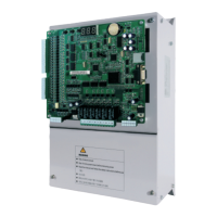
Shows the physical appearance and provides mounting dimensions for the NICE3000new controller.
Lists and describes optional parts for the NICE3000new, such as PG cards and car top boards.
Provides a table for selecting the appropriate braking resistor based on controller model and motor power.
Details installation environment and clearance requirements for the controller.
Illustrates terminal arrangements and provides descriptions for main and control circuits.
Covers dimensions, installation, and wiring descriptions for the Car Top Board (CTB).
Describes various display boards (HCB types) and their appearance and installation.
Details the Car Call Board (CCB), including its appearance, dimensions, and installation.
Explains the selection, wiring, and precautions for using MCTC-PG cards with encoders.
Guides the selection of peripheral devices like MCCBs, contactors, and reactors for the system.
Provides the overall electrical wiring diagram for the NICE3000new control system.
Details the arrangement and installation of shaft position signals like limit and slow-down switches.
Explains the functions of the onboard keypad buttons (PRG, UP, SET) and its menus.
Describes the LED operation panel, its indicators, keys, and three-level menu operation.
Details the LCD operator's keys, display structure, interfaces, and operation procedures.
Outlines the system commissioning procedure, including checks before commissioning.
Explains setting motor parameters and precautions for auto-tuning modes (with/no-load, shaft).
Describes conditions and steps for trial running at normal speed after auto-tuning.
Details the process for commissioning the door machine controller and checking feedback signals.
Discusses parameters influencing riding comfort and recommended adjustment methods.
Explains how to set and manage user passwords for parameter protection.
Covers system applications like emergency evacuation and parallel control.
Details parameter settings for opposite door control modes (old and new).
Explains the VIP function setup, including setting the VIP floor and parameters.
Explains the structure of function codes and the meaning of table columns.
Lists the 18 function code groups (F0-F9, FA-FD, FE, FF, FP, Fr) for the operation panel.
Presents the detailed function codes, parameters, setting ranges, defaults, and properties.
Describes basic parameters like control mode, command source, and running speeds.
Details motor parameters including encoder type, ratings, and auto-tuning settings.
Explains parameters for vector control, including speed and current loop settings.
Covers parameters for running control, such as startup speed, acceleration, and deceleration rates.
Details parameters related to floor information, leveling, and height adjustments.
Defines functions for input and output terminals, including safety and emergency signals.
Sets basic elevator parameters like floor configuration, parking, and service floors.
Provides parameters for elevator commissioning, including test functions and random running.
Details advanced functions like load cell tuning, pre-torque compensation, and anti-nuisance.
Covers time-related parameters for idle behavior, fan/lamp control, and system clock.
Defines parameters for keypad display selection and status parameter display.
Details parameters for door control, including protection times and standby states.
Explains protection functions such as overload, phase loss, and fault code logging.
Covers RS232 serial port parameters for host computer communication.
Configures elevator functions like collective modes, floor displays, and VIP service.
Describes parameters for fine-tuning elevator leveling accuracy and adjustment records.
Parameters related to factory settings, including user password and parameter updates.
Allows setting user passwords and managing parameter updates or fault record clearing.
Defines EMC, environments, and controller categories relevant to electromagnetic compatibility.
Outlines requirements for satisfying the European EMC directive, including installation environment.
Recommends EMC filters and AC input reactors and discusses their installation.
Details requirements for shielded cables, including their construction and installation precautions.
Provides guidelines for routing cables to minimize electromagnetic interference.
Offers solutions for common EMC interference issues like leakage tripping and communication problems.
Categorizes faults into five levels based on severity and outlines system handling actions.
Provides a table of fault codes, possible causes, solutions, and their severity levels.
| Brand | Suzhou MONARCH Control Technology Co., Ltd. |
|---|---|
| Model | NICE3000 New |
| Category | Controller |
| Language | English |