1D-6 Engine Mechanical:
Air Cleaner Element Removal and Installation
B718H11406034
Removal
1) Remove the fuel tank. Refer to “Fuel Tank Removal
and Installation in Section 1G (Page 1G-9)”.
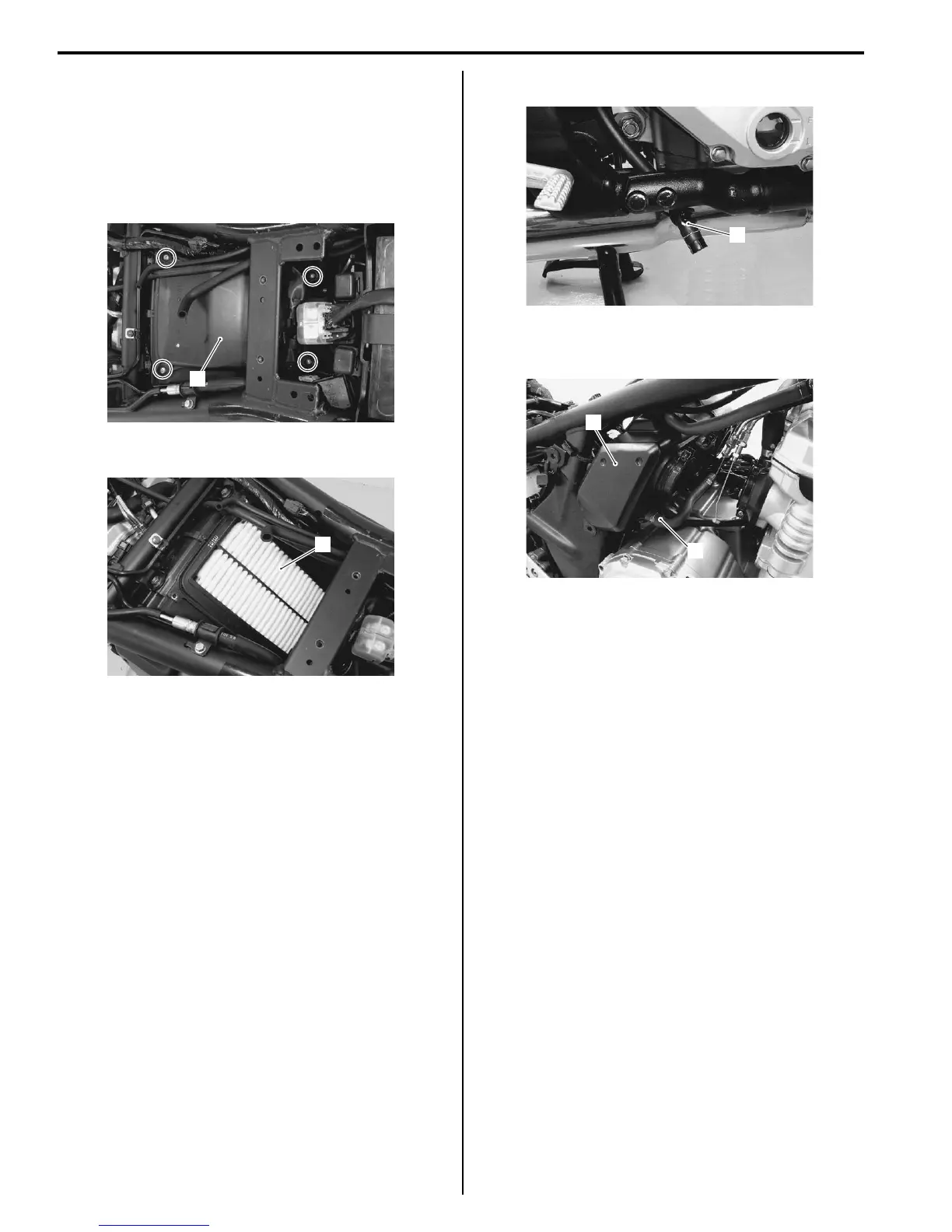
2) Remove the air cleaner cover screws.
3) Remove the air cleaner cover (1).
4) Remove the air cleaner element (2).
Installation
Installation in the reverse order of removal.
Air Cleaner Element Inspection and Cleaning
B718H11406035
Refer to “Air Cleaner Element Inspection and Cleaning in
Section 0B (Page 0B-3)”.
Air Cleaner Box Removal and Installation
B718H11406036
Removal
1) Remove the throttle body. Refer to “Throttle Body
Removal and Installation (Page 1D-9)”.
2) Remove the air cleaner cover and air cleaner
element. Refer to “Air Cleaner Element Removal and
Installation (Page 1D-6)”.
3) Release the drain hose from the clamp (1).
4) Disconnect the breather hose (2) and remove the air
cleaner box (3).
Installation
Install the air cleaner box in the reverse order of
removal. Pay attention to the following point:
• Route the hoses properly. Refer to “Throttle Body
Construction (Page 1D-8)”.
Throttle Cable Removal and Installation
B718H11406037
Removal
1) Remove the fuel tank. Refer to “Fuel Tank Removal
and Installation in Section 1G (Page 1G-9)”.
2) Remove the right handlebar switch box. Refer to
“Handlebar Removal and Installation in Section 6B
(Page 6B-3)”.
3) Remove the throttle cables as shown in the cable
routing diagram. Refer to “Throttle Cable Routing
Diagram (Page 1D-2)”.
1
I718H1140310-04
2
I718H1140311-01
1
I718H1140312-01
2
3
I718H1140313-01

 Loading...


