Wheels and Tires: 2D-8
6) Tighten two axle pinch bolts on the right fork leg to
the specified torque.
Tightening torque
Front axle pinch bolt (b): 23 N·m (2.3 kgf-m, 16.5
lb-ft)
7) Move the front fork up and down 4 or 5 times.
8) Tighten two axle pinch bolts on the left front fork leg
to the specified torque.
Tightening torque
Front axle pinch bolt (c): 23 N·m (2.3 kgf-m, 16.5
lb-ft)
9) Install the front wheel speed sensor mounting bolts.
(GSF1250A/SA) Refer to “Front Wheel Speed
Sensor Removal and Installation in Section 4E
(Page 4E-71)”.
10) Check the clearance between the front wheel speed
sensor and sensor rotor. (GSF1250A/SA) Refer to
“Front Wheel Speed Sensor Removal and
Installation in Section 4E (Page 4E-71)”.
Front Wheel Related Parts Inspection
B718H12406004
Refer to “Front Wheel Assembly Removal and
Installation (Page 2D-6)”
Tire
Refer to “Tire Inspection in Section 0B (Page 0B-19)”.
Front Brake Disc
Refer to “Front Brake Disc Inspection in Section 4B
(Page 4B-7)”.
Dust Seal
Inspect the dust seal lips for wear or damage. If any
defects are found, replace the dust seal with the new
ones. Refer to “Front Wheel Dust Seal / Bearing
Removal and Installation (Page 2D-9)”.
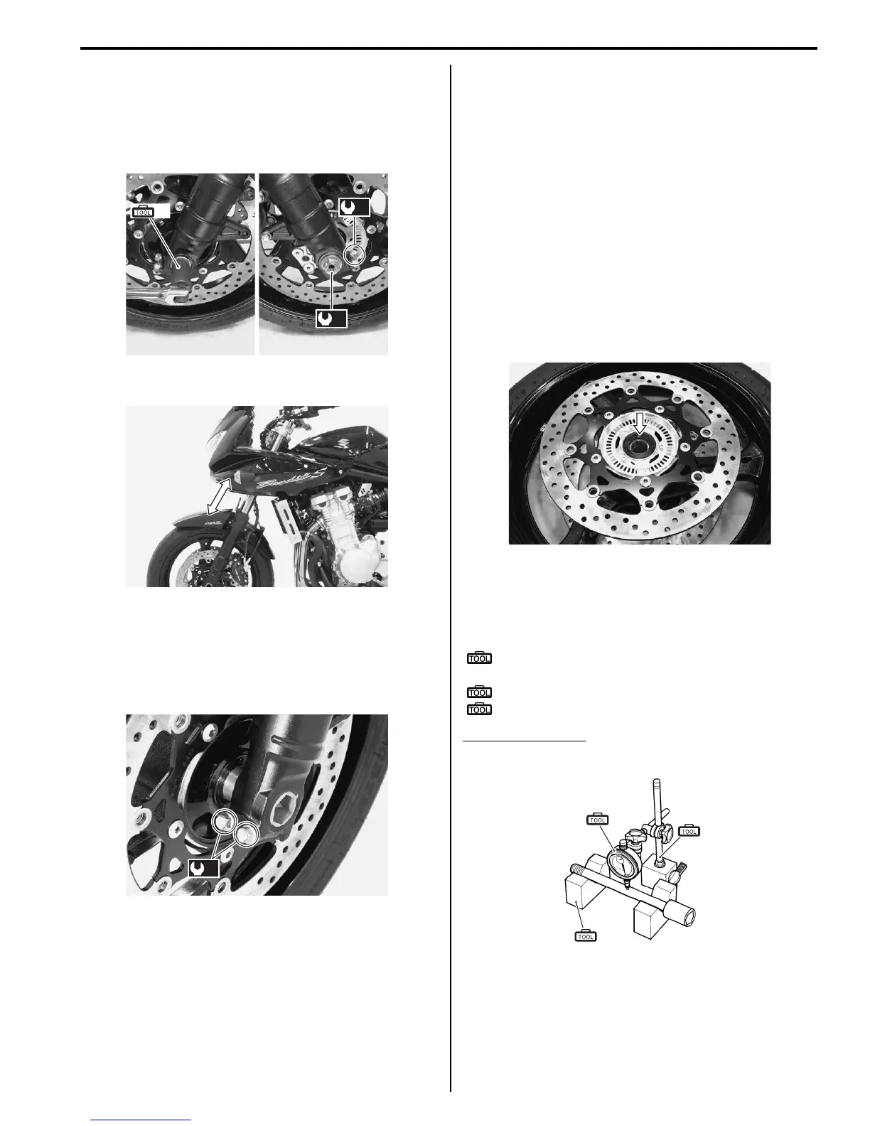
Wheel Axle
Using a dial gauge, check the wheel axle for runout. If
the runout exceeds the limit, replace the axle shaft.
Special tool
(A): 09900–20607 (Dial gauge (1/100 mm, 10
mm))
(B): 09900–20701 (Magnetic stand)
(C): 09900–21304 (V-block (100 mm))
Wheel axle runout
Service limit: 0.25 mm (0.010 in.)
(A)
(a)
(b)
I718H1240013-01
I718H1240014-02
(c)
I718H1240015-01
I718H1240017-02
(A)
(B)
(C)
I649G1240054-02

 Loading...


