Do you have a question about the SWAN Analytical AMI Silica and is the answer not in the manual?
Explains safety symbols (DANGER, WARNING, CAUTION) and mandatory signs.
Covers legal requirements, spare parts, and modifications for safe operation.
Details limitations and prerequisites for proper instrument function and sample handling.
Details application range, measurement method, sample handling, and system options.
Lists technical data including power, housing, sample requirements, and environmental limits.
Provides physical dimensions and mounting hole specifications for the instrument panel.
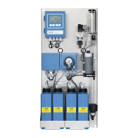
Visual guide to the instrument's components with clear labeling.
A comprehensive checklist to ensure all requirements and steps for installation are met.
Instructions and requirements for mounting the instrument panel correctly.
Step-by-step guide for installing the constant head assembly.
Procedures for connecting sample inlet and waste lines to the instrument.
Guide for installing the optional second sample stream module.
Instructions for connecting and configuring the AMI Sample Sequencer.
Details on wiring, cable thicknesses, and safety precautions for electrical connections.
Information on connecting the power supply and installation requirements.
Configuration and function of relay contacts and signal outputs for system control.
Details on available communication interfaces like Profibus, Modbus, HART, and USB.
Steps to activate the peristaltic pump, preparing it for operation after transport.
Guidance on preparing and inserting reagents into the instrument's system.
Procedure to establish and check sample flow through the instrument for correct operation.
How to program instrument parameters for external devices and operation limits.
Explains the function of control keys and how to interpret measured values and symbols on the display.
Overview of the instrument's menu structure for messages, diagnostics, maintenance, operation, and installation.
Step-by-step guide on how to modify instrument settings and parameters.
Procedure for performing a grab sample measurement for external samples or verification.
Outlines routine maintenance tasks and their recommended frequency for optimal performance.
Detailed steps for safely stopping the instrument before performing maintenance.
Procedures for replenishing or replacing reagent containers based on level indicators.
Procedures for verifying and calibrating the instrument to ensure accurate silica measurements.
Instructions for cleaning key components like the flow cell, photometer, and solenoid valve.
Guidance on replacing pump tubes, checking tube numbering, and replacing fuses.
Procedures for checking outputs/relays, filling reagent systems, and preparing for longer stops.
Explains how to identify and resolve slope errors during calibration.
Guidance on using grab sample for verification and troubleshooting deviations.
A comprehensive list of error codes, their descriptions, and suggested corrective actions.
Displays pending errors, maintenance tasks, and error history.
Provides access to view instrument and sample data without modification.
Used for calibration, simulation of outputs, and setting instrument time by service personnel.
Allows users to set limits, alarms, and other parameters for daily routine.
For system engineers to define parameters, assignments, and passwords during initial setup.
Detailed explanations for message lists, pending errors, and diagnostic information.
Explains calibration, service, fill system, and manual filling procedures.
Details on grab sample, sensors, relay contacts, logger settings, and programming.
Covers sensor setup, signal outputs, relay contacts, interface protocols, and miscellaneous settings.
Lists reagents used, their catalogue numbers, and product names for safety data reference.
Lists default settings for operation, sensors, signal outputs, relays, and installation parameters.
| Power Supply | 100-240 VAC, 50/60 Hz |
|---|---|
| Parameter | Silica |
| Detection Limit | 0.5 µg/L (ppb) SiO2 |
| Cycle Time/Response Time | Typically 10 - 15 minutes |
| Sample Flow Rate | 50 to 200 mL/min |
| Communication/Outputs | 4-20 mA, RS-232, Modbus |