1 MODEL 4OO TRANSCEIVER
C, Operation
(Cont)
3.
4.
Add a
.4T
or
.
5MF.
,
200 volt
caPacitor
across
the
key. This
capacitor rnay
be added internally
if
desired,
Switch the PHONE
-CW
control owe!
to
CW
position.
Then switch
the
Function Switch
to TRANS. to
transmit, and REC.
to receive.
5. In{ormation
on
a
sidetone
modifi-
cation for the 400 iB available on
request.
GENERAL
The
following
proceduies
are
given in
the order performed
during the
factory
alignrnent fo! the transceiver, For
home servicing only
partial
alignment
may be necessary. Read all
procedures
carefully
before commenc ing either
partial or complete
aliSnment. See
Figures 4 and
5Ior component
place-
rnent.
Equiplnent Requi!ed
L Caliblated
audio freqqency signal
generator, range
200 to 5000
cps.
2. 500 watt dummy load with output
3. Vacuum
tube voltmeter,
4, Walsco 2543
coil
adjustbent
tool.
5, Field
str€ngth meter
6. Calibrated RF Signal
Generator.
P!e
-Alignment
Conditions
l. Neutralizing
capacitorB
C4l3 aet
to rnid-point
and C3l6 Bet
to
approxirnately 3/4
turn lrom futl
cornpres 6ion.
2.
Peak lF transformers for maxi-
rnurn background noise
with
AF
and
RF
gain
Iull clockwi8e
(eithe!
bottom
or
top
core
adjustrnent).
3,
Loosely,
couple field strength
rn€ter to C3l?
(off
pin
9
of
V4)
with
alligator clip
on
cerahlc
capacitor
body.
TROUBLESHOOTING
4.
Transmit bias
potentiometer full
counter-clockwise
(maximurn
bias).
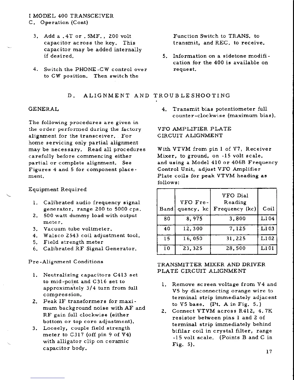
VFO AMPLIFIER
PLATE
CIRCUIT
ALIGNMENT
With VTVM from
pin I of
V7,
Receiver
Mixer, to
ground,
on
-15
volt
scale,
and
using
a
Model 410 or 4068 Frequency
Control
Unit, adjust Vr'O Amplifier
Plate coils {or
peak
VTVM
heading
as
followB:
D.
ALIGNMENT AND
Band
VFO Fle
-
VFO
Dial
Reading
Frequency
(kc)
Coil
80 3,800
Lt 04
40
12,300 7,125 L 103
l5
r 6, 050 Lt 0z
lo
28,500 Ll0l
TRANSMITTER
MIXER AND DRIVER
PLN,TE
CIRCUIT
ALIGNME NT
1,. Rernove
screen
voltage
florn
V4
and
V5 by disconnecting
orange
wire
to
telrninal strip irnrnediately
adjacent
to
V5
baBe.
(Pt.
A in Fig. 5.
)
2. Connect VTVM
across P.412, 4.7K
resistor
bet$/een
pins
I and 2 of
terminal strip irnmediately behind
bifilar coil
in cry6tal filter, !ange
-I5
volt scale,
(Points
B and C in
Fig.5).
t7
 Loading...