I
MODEL
4OO TRANSCEIVER
A, C ircuit
Theory
(Cont)
Authorities
agree that the
average voice
power
is l0 to
20 db below peak
vorce
power.
Normally
some
peak
clipprng in
the Power
Amplilier
(
an be tolerated,
and a
peak-to-average
ratio oJ
only 6 db
rray
sometimeg
occur. unde!
such a
condition,
the
average
power
input
will
be
125 \ratts,
and
plate
current will be
about 156 rna.
With an average Po'\r/er
Amplilier
efficiency of
55
per
cent,
plate
dissipation
wilt be
57 watts, or 28,
5
watts
per
tube. The 6HF5
is rated at
28 watt6 continuous duty
cycle in normal
TV service.
Thus it can be
seen that
under normal
operating conditions
th€
PA tubes in
the Swan 400
are
not
being
driven
very
hard.
Only dLrring
the tune
up is
there any need
to exercise caution
by lirniting
the length of
time the unit
is
held
in the TUNE position
to about
30
seconds
at a time,
B.
INSTALLATION
CENERAL
The
Swan 400 traogceiver has
been
designed to
provide
the
utmost in ease
of
operation, stability, versatility,
arld
enjoyment.
Maximum enjoyment Irorn
your
Swan
will depend to
a
great
extent
on the installation. For
fixed station or
portable
use, operation
with the
Model
I I?XB or I t?XC power
supply
provides
a
(
ompa( t dr rdngement with
maxrrnum
ease oI
op< ration.
AII swrt( hrn8 is
performed in the transceiver.
For
mobile installations, the Model
l4-I1?
supply
provides switching
ar rangements,
and speaker
output rnay be
fed through
the car broadcast receiver 6peaker,
POWER SUPPLY
The
Swan
Models II?XB or
ll?XC
power
Eupplies
provide
aU neces6ary
voltages
required by the transceiver.
The
supplies corne equipped
with a
pre-wired
plug
and
cable,
all !eady for plu8ging
into the transceiver, The
Model l4-II7
supply lor mobile operation
includes
all
necessary
cables,
conn€ctor plug,
luses,
and installation
hardwa!e.
The
Jones
plug
lor connection to the transcervet
ts
furnished with
the unit.
8
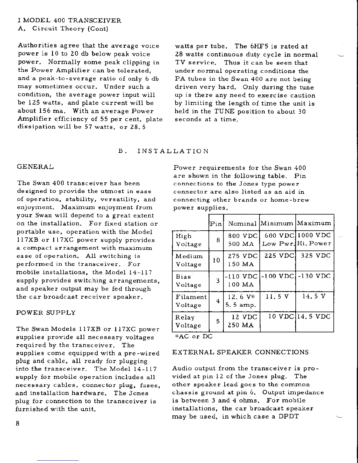
Power requirements for the
Swan 400
are shown
in
the
following table. Pin
connections
to the Jones type power
connector
are also listed as an aid in
connecting
other brands or horne-brew
power
eupplies.
+AC
or
DC
EXTERNAL
SPEAKER CONNECTIONS
Audio output from the transceiver is
pro-
vided
at
pin
12 of the
Jones
plug.
The
other speaker lead
goes
to the common
chassis ground
at
pin 6. Output impedance
is between 3 and 4 ohms. For mobile
installations, the car broadcast speaker
rnay be used, in ]vhich case a DPDT
Pin Nornrnal
Minirnum Maximurn
High
Voltage
8
800 vDc
5OO
MA
600 VDC
1000 vDc
lli. Powe r
Mediurn
Voltage
t0
z? 5 vDc
I50MA
225 VDC
325
VDC
Bias
Voltage
3
-
110 vDc
IOO MA
-100
vDc
-I30
VDC
Filament
Voltage
4
12.6 Y'N
5.5 alnp.
II.5V
t4.5 v
Relay
Voltage
5
r2 VDC
250 MA
IO
VDC
14. 5
VDC
 Loading...