SWS Warning Systems Inc. – 7695 Blackburn Pkwy., Niagara Falls, ON, Canada
Tel: 1-877-357-0222 | Fax: 1-905-357-9122 | Email: sales@swssafety.com
300385 Rev. 2
2 | P a g e
Select a surface where the light is visible and free of obstruction.
Mounting brackets are available from the manufacturer.
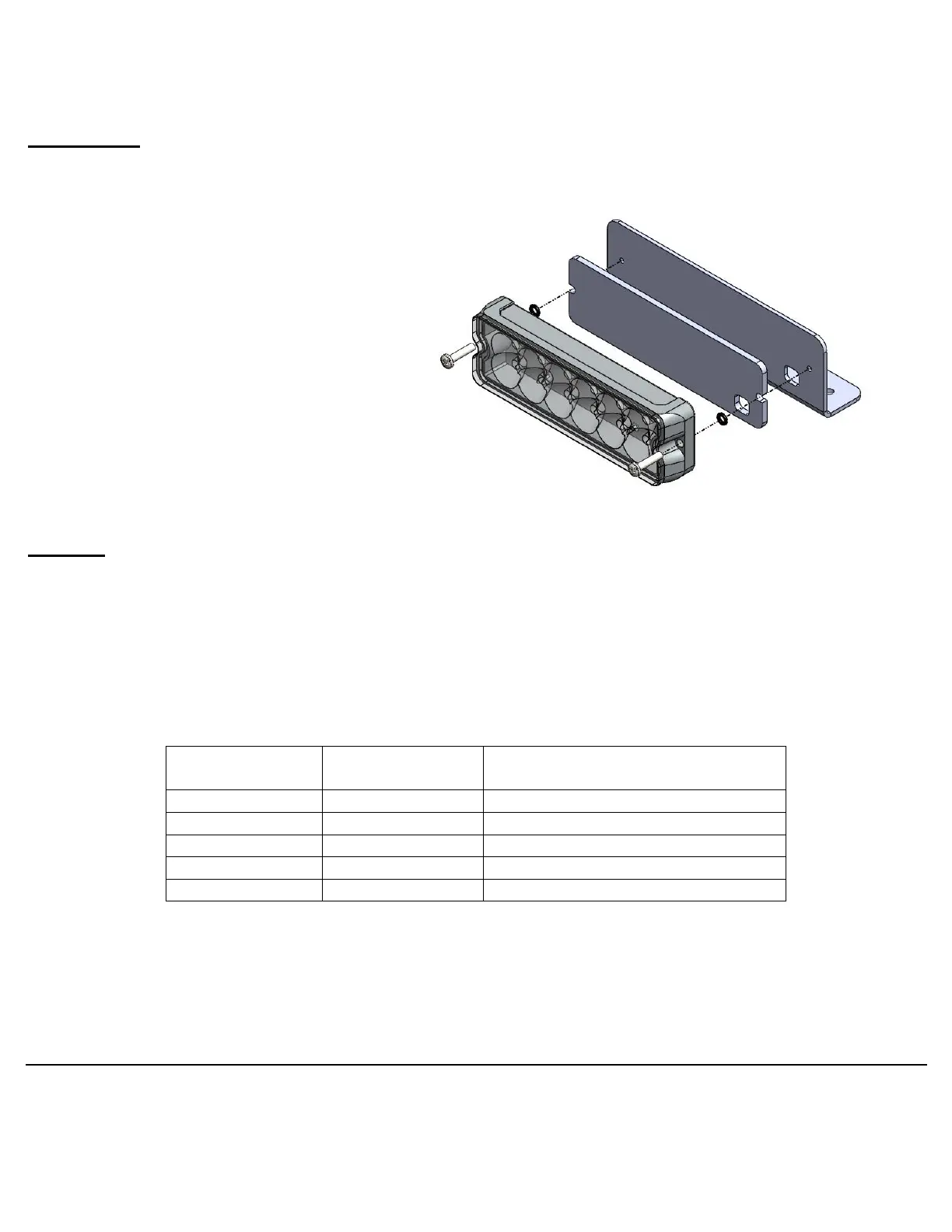
Mounting
The light is to be mounted with the long edge parallel to the road surface.
1. If you are not using a manufacturer
bracket; using the foam pad as a
template, drill two 7/64” (or #36 drill bit)
holes 4.75” apart.
2. Drill a hole for the wires as well.
3. Pass the screws through the base and
place the rubber o-rings onto the
threads.
4. Place the foam pad onto the back of the
base.
5. Screw the lighthead to the surface, but
do not over tighten.
Wiring
All extension wires need to be appropriately sized depending upon the length that they are to travel.
SWS recommends a minimum of 20AWG wire for short runs and that for every additional 10ft. of
length, the gauge be increased (i.e. for a length of 11ft, the minimum gauge for power wires would be
18AWG).
If you are unsure of your wire gauge or want to use a lesser gauge, check the voltage at the product
wire connection to ensure the light will receive adequate power.
Pattern Select, Sync/Alt Select
Colour Select (where applicable)
 Loading...