L
lanechelseaAug 5, 2025
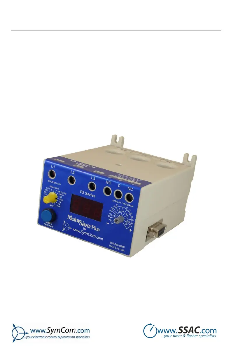
What to do if the SymCom Power distribution unit display alternates “LPr”1 with “RUN”?
- JJames JohnsonAug 5, 2025
If the SymCom Power distribution unit display alternates “LPr”1 with “RUN”, the overload relay has tripped on low power (LPr) and is timing down RD3 before restarting. To correct this issue, check programmed limits by turning the MODE SELECT knob and return the LPr setpoint to “30” to stop the low power fault.