565E
9
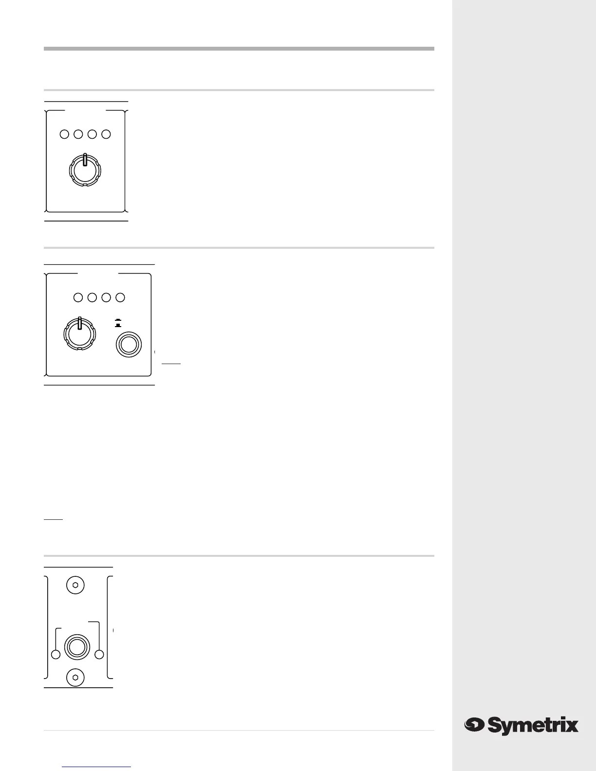
The Limiter Controls
THRESHOLD control - The THRESHOLD control sets the level to which the
input signal must rise before limiting occurs. Once the audio input signal
rises above this threshold, the output gain will be reduced by a ratio of 20:1
(i.e. an above-threshold signal increase of 20 dB at the input would result in
only a 1 dB signal increase at the output).
LED display - The LED display indicates the amount by which the output
level has been reduced by the limiter.
CH1 LIMITER
-12 -6 -9 -3
+5
-3 +13
-12
BYPASS
THRESHOLD (dBu)
CH1 OUTPUT
-10 0dBu CLIP-20
IN
0
+10-10
BYPASS
+20
-20
GAIN (dB)
STEREO LINK
STEREO
DUAL MONO
The Output Controls
GAIN control - The GAIN control sets the final output signal level.
This control can be used to increase the output level, up to +20 dB,
or to decrease the output level, by as much as -20 dB. This control
can be used, if needed, to restore signal level lost by compression or
limiting, to make up for the 6dB drop in output level that occurs when
you connect an unbalanced cable to the 565E’s output, or to reduce
the 565E’s output level to prevent overdriving the input stage of the
next device in the signal chain.
Note The unity gain position (0) of the GAIN control is referenced
to the balanced output connector. If you are using the
unbalanced output, unity gain occurs when the GAIN control
is set to +6 dB.
LED display - The LED display indicates the final output signal level. Generally, the first two or
three LEDs should light when signal is present, but the CLIP LED should never be on solidly. It is
usually all right if the clip LED flashes occasionally, on peaks in the program material. If you see
the CLIP LED light, monitor your final signal destination to be sure that you are not creating
distortion by running audio levels that are too hot.
IN/BYPASS switch - The IN/BYPASS switch engages the 565E’s processing circuitry when it is set to
the “IN” position, and places the 565E’s processing section in bypass when the switch is set to the
“BYPASS” position.
Note This is not a hard-wire bypass; the 565E will not pass signal unless the unit is powered
and turned on.
The Stereo Link Control
STEREO/DUAL MONO switch - The STEREO/DUAL MONO switch is used to select
either Stereo or Dual Mono mode. In Stereo mode both channels of the 565E
respond to the Channel 1 controls, and the Channel 2 controls have no effect. In
Dual Mono mode the 565E’s two channels operate independently, with each
channel responding to its own controls. Typically, the 565E would be switched to
Stereo mode when Channel 1 and Channel 2 are being fed stereo left and right
inputs. Set the 565E to Dual Mono mode when Channel 1 and Channel 2 are being
fed signals that you wish to process separately (such as a vocal signal being fed to
Channel 1 and a bass guitar signal being fed to Channel 2).
DUAL MONO LED - Indicates that the 565E is switched to Dual Mono mode.
STEREO LED - Indicates that the 565E is switched to Stereo mode.