■ Connect 120 VAC line voltage to the primary side of the
transformer as displayed in Figure 1.
12V
6V
T
coil
connections
Relay 12 VDC @ <80mA
(customer supplied option)
Remote monitoring
system connections
Temperature probe and
1/4" NPT male tting
Water hammer
arrestor (optional)
Tee tting
(required, see
options)
Alarm
control
module
Water ow
Transformer
12 VAC/15 VA
Solenoid valve (optional)
12 VDC, 10 Watts max
120 VAC Power
25'probe cable
(optional lengths)
■ Connect the 12 VAC secondary side of the transformer to
the 12 VAC power input terminals on the back of the alarm
control module as identied in Figure 2 below. Note that
there is no polarity required for the input terminals.
ON
OFF
Fuses #229
1.5A / 250VP
12 VAC
power input
12 VDC valve
power output
(optional)
Temperature
input probe
DIP Switches
Rear view of Alarm Control Module
12 VDC relay
power output
(optional)
■ Temperature Probe - Plug probe into the connector on
the backside of the control module as identied in Figure2
above. Note that the connectors are keyed and will only mate
in one direction. (optional cable lengths are available)
■ Solenoid Valve (optional) -
Connect coil wires between the
solenoid valve and the valve power output terminals on the
back of the control module as identied in Figure 2 above.
Note that there is no polarity required between connections.
High Temperature Audio Visual Alarm System, HTA-100
Installation and Service Instructions
TempControl
®
General Information
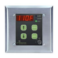
■ Alarm System - TempControl High Temperature Audio
Visual Alarm System will monitor, alert and alarm when
water temperature exceeds preset limit. It best ts
applications where there is a critical need to accurately
monitor and control warm or hot water temperature.
■ Solenoid Valve (optional) - When alarmed, the valve is
de-energized and closes to provide complete shutdown of
the water ow.
■ Relay (customer supplied option) - Installed relay enables
remote monitoring of alarm control module.
■ Caution Set Point - is the lower of the two set point
temperatures that alerts when the output water is
approaching an undesirable temperature limit.
■ Alarm Set Point - Once the output temperature reaches the
alarm set point, the system goes into full alarm mode.
Installation
Important: All piping should be thoroughly
ushed prior to installation to prevent debris from
interfering with the solenoid operation. Do not run
solenoid power and temperature probe through
same conduit.
Piping
■ Tee Fitting - Required; appropriate size tting for
application purchased seperately (see options).
■ Temperature Probe - Locate probe as far downstream from
mixing valve as is reasonably possible.
a. Slide connector nut and ferrule piece over the probe.
b. Slide probe 1/2” to 2/3” into the tee tting.
c. Slide the ferrule and connector nut down the probe sha
and tighten in place.
■ Solenoid Valve (optional, 12 VDC, 10 Watts, normally
closed) - Install valve directly before the temperature probe in
any orientation. Make note of the correct direction of the water
ow as marked on the valve.
Electrical
■ Mount the 4" x 4" supplied mounting box in a dry location
within wiring reach of the temperature probe and solenoid
valve if used.
■ Mount supplied transformer.
(120 VAC – 12 VAC/15 VA UL listed, CSA certified class 2)
Figure 1
Figure 2
For California Residents
WARNING: is product contains chemicals known to the State of California to cause cancer, birth defects, or other reproductive harm.