INSTALLATION GUIDELINES
Ceiling: Detector should be at least 12 inches from any wall.
Wall: Detector should be at least as high as a light switch, and at least six
inches from the ceiling.
• Do not install in any environment that does not comply with the detec-
tor’s environmental specifications
• Install in accordance with NFPA 720–the Standard for the Installation of
Carbon Monoxide (CO) Detection and Warning Equipment
• As of 2009, NFPA 720 defines standards for both commercial and resi-
dential installations of CO detectors. If the installation can be interpreted
as a commercial application, consult the section of NFPA 720 that out-
lines commercial applications.
• For example, Chapter 5.5.5.3.1 states that carbon monoxide detectors
shall be installed in accordance with manufacturers published instruc-
tions in the following locations:
(1) On the ceiling in the same room as permanently installed fuel burn-
ing appliances
(2) Centrally located on every habitable level and in every HVAC zone of
the building
• If the installation can be interpreted as residential, consult the section of
NFPA 720 that outlines residential applications.
• For example, chapter 9.4.1.1 states that carbon monoxide alarms or
detectors shall be installed as follows:
(1) Outside each separate dwelling unit sleeping area in the immediate
vicinity of the bedrooms
(2) On every level of a dwelling unit, including basements
(3) Other locations where required by applicable laws, codes or standards
MOUNTING
The CO1224T/CO1224TR can be ceiling-mounted or wall-mounted:
1. To a single gang box.
2. Direct mount to ceiling or to wall using drywall fasteners.
INSTALLATION
WIRING INSTALLATION GUIDELINES
All wiring must be installed in compliance with the NFPA 70, National Electrical
Code, applicable state and local codes, and any special requirements of the local
Authority Having Jurisdiction (AHJ).
Proper wire gauges should be used. The conductors used to connect carbon
monoxide detectors to the alarm control panel and accessory devices should
be color-coded to reduce the likelihood of wiring errors. Improper connections
can prevent a system from responding properly in the event of a CO.
The screw terminals in the mounting base will accept 14-22 gauge wire. Wire
connections are made by stripping approximately
1
⁄4
˝ of insulation from the
end of the feed wire, inserting it into the proper base terminal, and tightening
the screw to secure the wire in place. Do not put wires more than 2 gauge
apart under the same clamping plate.
WARNING: This product does not have a local audible trouble signal, and
may fail without supervision if trouble loop remains unconnected.
WARNING: Gas detectors on a zone that is bypassed may not signal a trouble
condition. Do not bypass zones used for gas detectors.
Wiring diagrams located on page 4, Figure 4.
WARNING
Remove power from alarm control unit or initiating device circuits before in-
stalling detectors.
1.
Using a small, flat head screw driver, push in the small tab located on the
underside of the detector. Once the snap is loosened, lift the bottom end
of the cover up and unhinge the top to remove the cover.
2. Wire the detector base screw terminals per Figure 5.
3. Screw the base of the detector onto a single gang electrical box, or to the
surface of the wall or ceiling. Use the hardware included in the packaging.
4. If mounting with the System Sensor replacement plate model CO-PLATE*:
* Hold replacement plate over desired mounting area.
* Use hook feature to hold CO1224T onto the replacement plate.
* Mount detector and plate together using hardware provided with the
CO1224T.
5. Hinge the top portion of the cover onto the base; with the cover at a 45
degree angle, fit the hinges into the slots of the base.
6. Push the unhinged bottom portion of the cover down until it snaps into place.
7. After all detectors have been installed, apply power to the alarm control unit.
8. Test each detector as described in Testing.
9. Notify the proper authorities that the system is in operation.
CAUTION
Airborne dust particles can enter the detector. System Sensor recommends the
installation of detectors after construction or any other dust producing activ-
ity. Carbon monoxide detectors are not to be used with detector guards unless
the combination has been evaluated and found suitable for that purpose.
TESTING
Detector must be tested after installation.
NOTE: Before testing, notify the proper authorities to avoid any nuisance
alarms.
Ensure proper wiring and power is applied. After power up, allow 80 seconds
for the detector to stabilize before testing.
Test the CO1224T/CO1224TR detector as follows:
1. A test button is located on the detector housing (See Figure 4).
2. Use the tip of your finger to press and hold the test button for 1-4
seconds.
3. If the sounder beeps twice in the Temporal 4 tone and the LED’s light up,
the detector is operational.
4. The detector now enters Realtest speed up test mode indicated by a
quickly blinking green LED. See Functional Gas Test section for instruc-
tions on testing with canned CO.
If a detector fails the above test method, its wiring should be checked. If the
detector still fails after rewiring, it should be replaced.
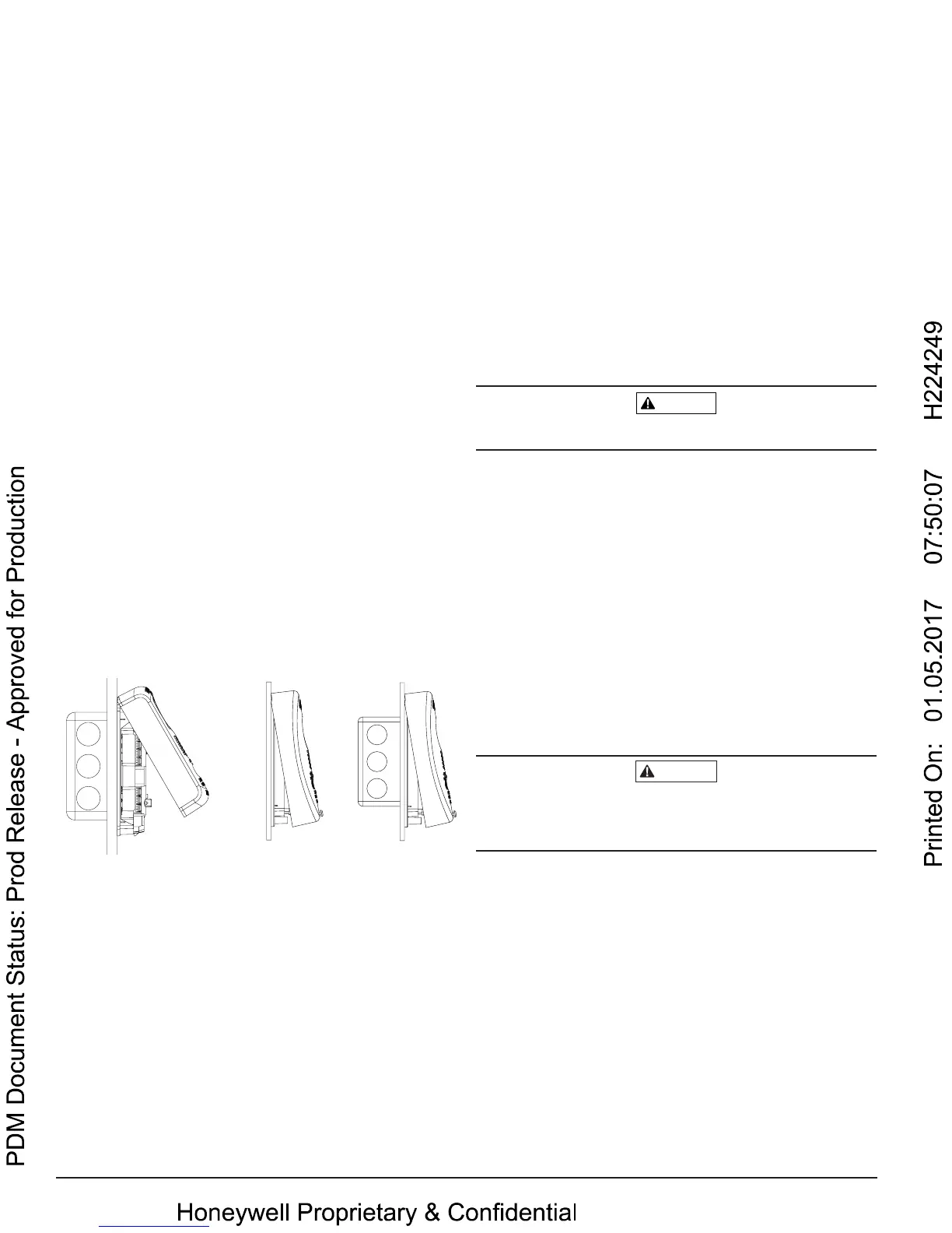
S0320-00
FIGURE 2. MOUNTING OF DETECTOR:
CO1224T CO1224TR
S0296-01
2 I56-3111-012
10-28

 Loading...
