System Sensor warrants its enclosed product to be free from defects in materials and
workmanship under normal use and service for a period of three years from date of
manufacture. System Sensor makes no other express warranty for the enclosed product.
No agent, representative, dealer, or employee of the Company has the authority to in
-
crease or alter the obligations or limitations of this Warranty. The Company’s obligation
of this W
arranty shall be limited to the replacement of any part of the product which is
found to be defective in materials or workmanship under normal use and service during
the three year period commencing with the date of manufacture. After phoning System
Sensor’s toll free number 800-SENSOR2 (736-7672) for a Return Authorization number,
send defective units postage prepaid to: Honeywell, 12220 Rojas Drive, Suite 700, El Paso
TX 79936, USA. Please include a note describing the malfunction and suspected cause
of failure. The Company shall not be obligated to replace units which are found to be
defective because of damage, unreasonable use, modifications, or alterations occurring
after the date of manufacture. In no case shall the Company be liable for any consequen
-
tial or incidental damages for breach of this or any other Warranty, expressed or implied
whatsoever, even if the loss or damage is caused by the Company’s negligence or fault.
Some states do not allow the exclusion or limitation of incidental or consequential dam
-
ages, so the above limitation or exclusion may not apply to you. This Warranty gives you
specific legal rights
, and you may also have other rights which vary from state to state.
THREE-YEAR LIMITED WARRANTY
FCC STATEMENT
This device complies with part 15 of the FCC Rules. Operation is subject to the following two conditions: (1) This device may not cause harmful interference, and (2) this device must
accept any interference received, including interference that may cause undesired operation.
NOTE: This equipment has been tested and found to comply with the limits for a Class B digital device, pursuant to Part 15 of the FCC Rules. These limits are designed to provide
reasonable protection against harmful interference in a residential installation. This equipment generates, uses and can radiate radio frequency energy and, if not installed and used
in accordance with the instructions, may cause harmful interference to radio communications. However, there is no guarantee that interference will not occur in a particular installa
-
tion. If this equipment does cause harmful interference to radio or television reception, which can be determined by turning the equipment off and on, the user is encouraged to try
to corr
ect the interference by one or more of the following measures:
– Reorient or relocate the receiving antenna.
– Increase the separation between the equipment and receiver.
– Connect the equipment into an outlet on a circuit different from that to which the receiver is connected.
– Consult the dealer or an experienced radio/TV technician for help.
Please refer to insert for the limitations of Carbon Monoxide Detectors
S0313-01
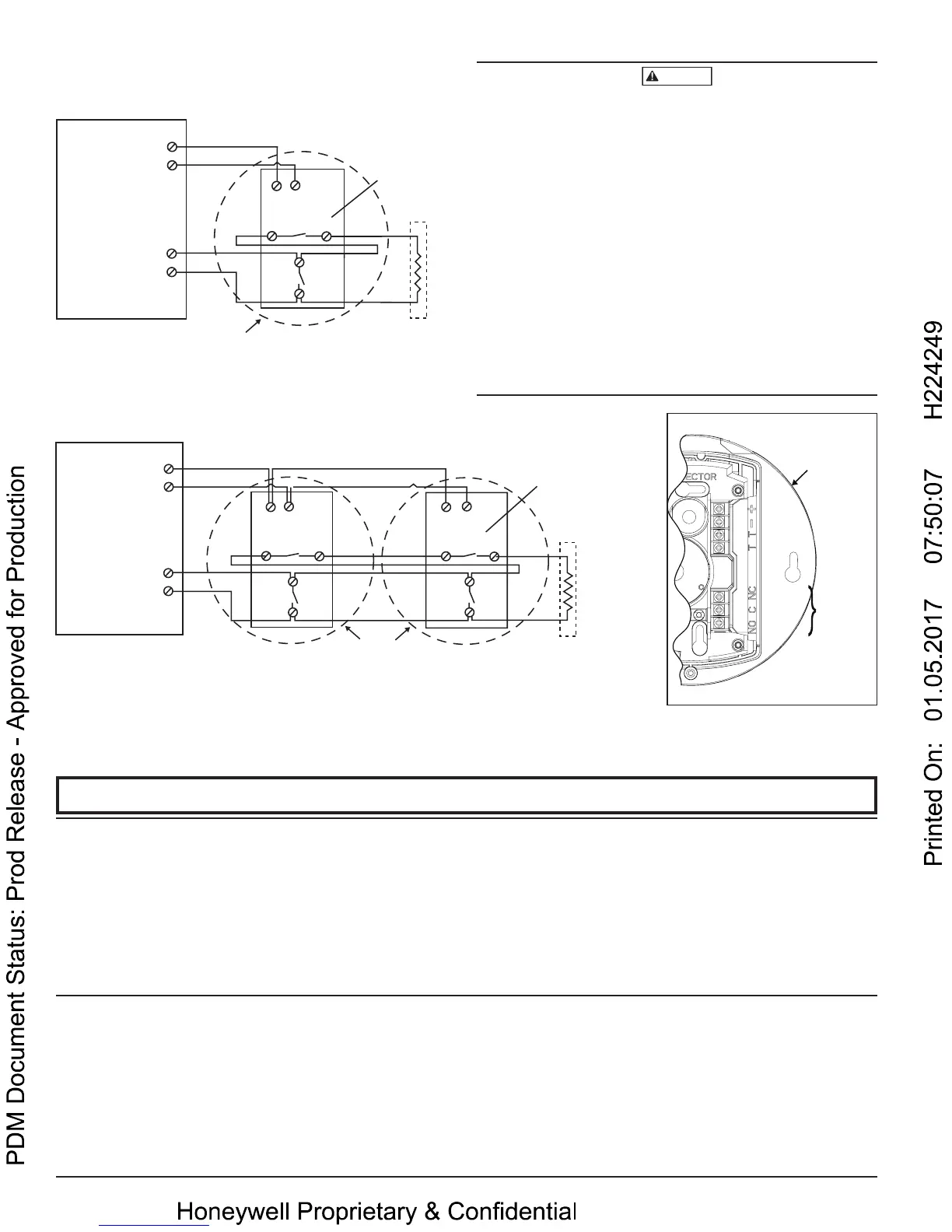
FIGURE 5. WIRING DIAGRAM:
S0322-01
POSITIVE
NEGATIVE
TROUBLE
TROUBLE
NORMALLY
CLOSED
NORMALLY
OPEN
COMMON
}
POWER
OUTER CIRCLE IS FOR
CO1224TR ONLY
}
TROUBLE
RELAY
ALARM
RELAY
Input powered (12 or 24 VDC) from UL Listed Fire/Burg Control Panel (Class 2).
NON-RESETTABLE PWR
CO ZONE
UL LISTED
PANEL
+
−
ALARM
INITIATION
CONTACTS
EOL RESISTOR
SPECIFIED BY PANEL
MANUFACTURER
C
NO
TT
+ −
CLOSED WITH
POWER APPLIED
AND NO FAULT
DETECTED
SINGLE UNIT, SINGLE ZONE, 4 CONDUCTOR CABLE
CO1224TR
ROUND CO
NON-RESETTABLE PWR
CO ZONE
UL LISTED
PANEL
+
−
SUPERVISORY TROUBLE CONTACTS
ALARM
INITIATION
CONTACTS
ALARM
INITIATION
CONTACTS
FIRST CO1224
DETECTOR
IN LOOP
CO1224TR
ROUND CO
DETECTOR
LAST CO1224
DETECTOR
IN LOOP
EOL RESISTOR
SPECIFIED BY PANEL
MANUFACTURER
C
NO
C
TT TT
+ −
+ −
CLOSED WITH
POWER APPLIED
AND NO FAULT
DETECTED
MULTIPLE UNIT, SINGLE ZONE, 6 CONDUCTOR CABLE
NO
S0314-01
CAUTION
It should be noted the installation, operation, testing and maintenance of
the CO1224T/CO1224TR is different than System Sensor conventional 4-wire
smoke detectors, such as the i3 Series. Below are specific installation require-
ments for the CO1224T/CO1224TR:
• Connect to a non-resettable power supply
• Connect to a non-fire zone: Per NFPA 720 section 9.6.7.2 the CO1224T/
CO1224TR shall not be connected to a zone that signals a fire condition
• Per NFPA 720 section 9.6.7, do not connect the CO1224T/CO1224TR on
a zone with other fire or intrusion initiating devices - i.e. do not connect
on the same zone as smoke detectors
• Wiring of the trouble relay is mandatory: Per UL Standard 2075 section
17.1.1 a detector shall send a trouble signal to the control panel upon an
open circuit, a ground fault, sensor removal or sensor end of life
• If wiring one CO1224T/CO1224TR per zone: Use 4 conductors
• If wiring multiple CO1224T/CO1224TR detectors per zone: Use 4 con-
ductors from panel to first CO1224T/CO1224TR, then use 6 conductors
from the second CO1224T/CO1224TR to other detectors on the zone
System Sensor® is a registered trademark of Honeywell International, Inc.
4 I56-3111-012
©2016 System Sensor. 10-28
 Loading...

