_____________________________________________________________________________________________________
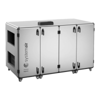
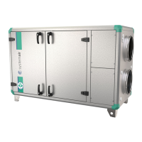
Topvex TR03, TR04, TR06 Installation description
205354 Systemair AB
6
Fig. 4
Description
A.
Frost protection sensor (standard)
B.
Internal dimension 15R (1/2’’)
C.
Pump, secondary circuit
D.
Non return valve
E.
Valve actuator + water valve (accessories)
F.
Pump, primary circuit
Fig. 5
Description Description
1.
Alarm button
7.
Connection block
2.
Alarm LED
7a.
Yellow cable
3.
Write enable LED
7b.
Orange cable
4.
OK button
7c.
Red cable
5.
Clearing button
7d.
Brown cable
6.
Mounting holes
7e.
Black cable
2-wa
valve
3-wa
valve
 Loading...