16
| Installation
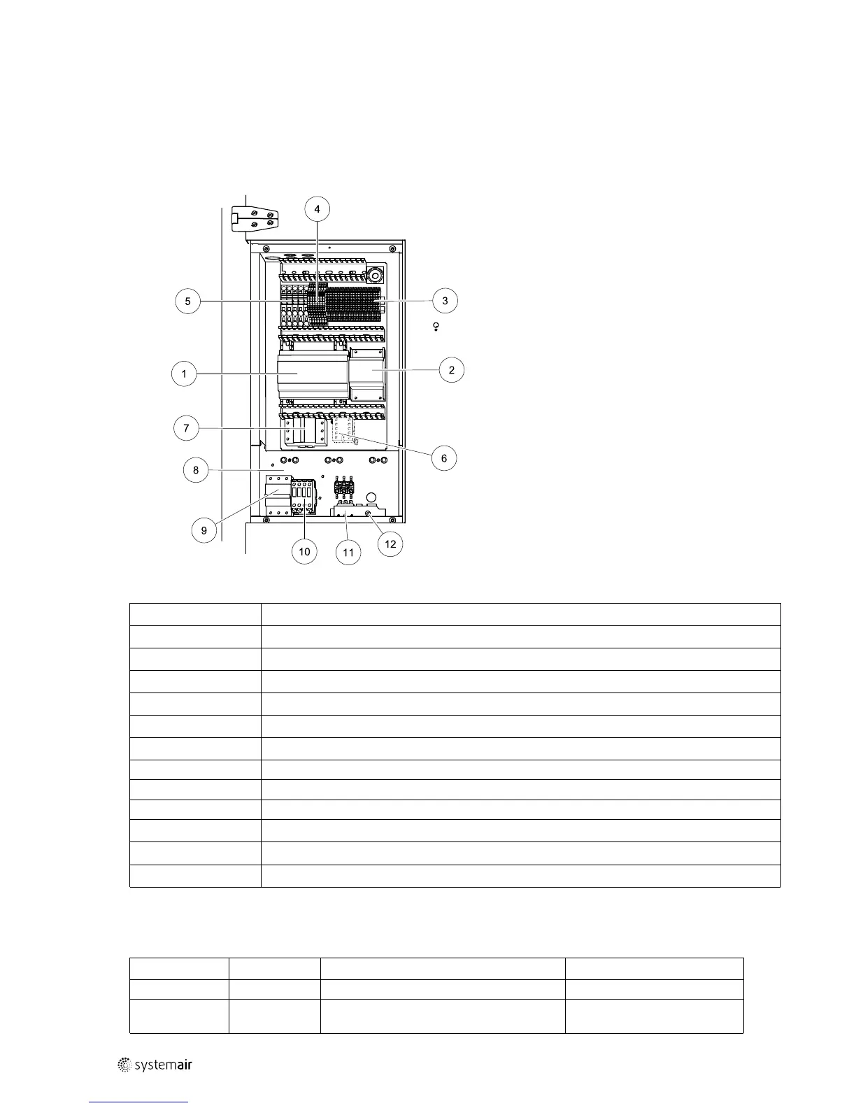
4.5.2.1 Electrical connection box, Components
Topvex SR/TR 03-06 are equipped with a built in regulator and internal wiring (figure 13).
The figure shows the electrical connection box for the Topvex TR 03-06 units. The connection box for the Topvex SR
03-06 has the same layout and components with the difference that the electrical heater is situated in a separate
compartment.
PPoossiittiioonn
ddeessccrriippttiioonn
1
Regulator E-28 WEB
2
Transformer 230/24V AC
3
Terminals for internal and external components
4
Terminals for internal wiring
5
Terminals for mains supply to the unit
6
Contactor (K2) Pump control water (HW units only, not present in EL-units)
7
Automatic fuse
8
Electric heater frame
9
Automatic fuse for heater
10
Contactor (K3) for control of EL heater
11
Thermostat (EL units)
12
Manual over heat protection reset (EL units)
4.5.2.2 Topvex External Connections
Table 3 Connections to external functions
TTeerrmmiinnaall bblloocckk
DDeessccrriippttiioonn
RReemmaarrkk
PE
Ground
N N
Earthed neutral (supply voltage)
Used for phase 230V 1~ and
400V 3~
 Loading...