Applications:
TA thermostats are used
together with TA thermostat valves for
controlling the temperature of each
room individually.
Function:
When room temperature ex-
ceeds the thermoststat's setting mark,
the expansion medium increases in
volume and starts closing the valve.
When room temperature falls, the volu-
me decreases and the valve's return
spring opens the valve.
Nominal temperature range:
The ther-
mostat's various settings provide the
following (approximate) room tempera-
tures:
Setting scale
01121314151 6
I
7
1
8
1
9
+
Approx.8 10 12 14 16 18 20 22 24 26
"C
These temperatures apply for a nominal
lift according to SIB M785 During nor-
mal operating conditions the desired
room temperature is maintained with a
maximum deviation of
k
1 "C. An increa-
se in temperature of approx 2°C on the
sensor above desired temperature set-
ting is necessary for the thermostat to
close the valve entirely.
Setting scale for RVT 50
C
0--
01
*2*3*4*5*6*7*8*9*+
6 8
10
12 14 16 18
M
22
24 26
OC
Approx. 43
46
50
54
57 61 64
68
72 75 79
"F
Max working temperature:
The ther-
mostat should not be subjected to tem-
peratures above 50 "C or below -20 "C.
Anwendungsbereich:
TA Thermostat-
kopfe werden zusammen mit TA Ther-
mostatventilen fur individuelle
Raum-
temperaturregelung verwendet.
Funktion:
Wenn die Raumtemperatur
uber den am Thermostat eingestellten
Wert ansteigt, dehnt sich das
Expansion-
smittel aus und beginnt, das Ventil zu
schlie0en. Bei sinkender Raumtempera-
tur verringert sich das Volumen des
Expansionsmittels, und die Ruckholfe-
der offnet allmahlich. das Ventil.
Nomineller Temperaturbereich:
Die
verschiedenen Thermostat-Einstellung-
en ergeben ungefahr die nachstehenden
Raumtemperaturen:
Einstellskala
~1121314151
6
I
7
1
8
1
9+
Ca. 8 10 12
14
16 18 20 22 24 26
"C
Die angegebenen Temperaturwerte gel-
ten bei nominellem Hub gema0 SIB
M785 Bei normalen Betriebsverhalt-
nissen wird die eingestellte Raumtem-
peratur mit einer max. Abweichung von
f
1
K
konstant gehalten. Damit der
Thermostat das Ventil ganz schlieBt, ist
eine Temperaturerhohung am Fuhlkor-
per von ca. 2
K
Bber den eingestellten
Wert erforderlich.
Einstellskala fur RVT 50
C
0
01
*2*3*4* 5*6*7*8*9*+
6 8 10 12 14 16 18
20
22
24 26
"C
Ca.
43
46
50
54
57
61 64
68
72 75 79
OF
Max. Betriebstemperatur:
Das Ther-
mostatteil darf keinen hoheren Tempe-
raturen als 50 "C, und keinen niedrige-
ren Temperaturen als -20 "C ausgesetzt
werden.
Range
limit:
See
page
5
Max. Begrenzung:
Siehe Seite 5
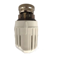
Marking:
The thermostats bear the con-
trol marks of the Swedish Board of
Urban Planning, of DIN and of AFNOR.
In addition, year and week of manufac-
ture (i.e.
8614)
is stamped under the
handwheel.
Kennzeichnung:
Das Thermostatteil ist
mit den Kontrollmarken von Planverket
(Schweden), DIN und AFNOR
(Frank-
reich) versehen.
Unter dem Drehgriff sind Herstellungs-
jahr und -woche aufgedruckt, beispiels-
weise 8614.
Application:
Les tetes thermostatiques
TA conviennent aux robinets ther-
mostatisables TA monotube et bitube.
Fonction:
Leur r6le essentiel est de
maintenir constante la temperature sou-
haitee dans un local et de valoriser les
apports gratuits. Lorsque la temperature
ambiante augmente, I'element sensible
expansible se dilate, provoquant ainsi
la
fermeture progressive du robinet. In-
versement, lorsque la temperature
ambiante sera inferieure au point de
consigne, I'element sensible agira de
telle sorte que le robinet se reouvrira
progressivement.
lntervalle nominal de reglage:
Les dif-
ferentes positions de reglage de la tete
thermostatique correspondent approxi-
mativement aux temperatures ambian-
tes ci-dessous:
Echelle de reglage:
wl1213141516 17
1
8
1
9+
env.
8 10 12 14 16 18 20
22 24 26
"C
Les temperatures indiquees ci-dessus
sont valables pour une hauteur mano-
metrique nominale selon SIB M785
Dans des conditions normales de servi-
ce, la temperature ambiante souhaitee
sera obtenue
a
f
1 "C prs. Pour entrai-
ner la fermeture du robinet, la tempera-
ture au niveau de I'element sensible
devra etre de 2°C superieure
a
la con-
signe.
Echelle de reglage pour RVT 50
C
0--
01
*2*3*4*5*6*7*8*9*+
6 8 10 12 14 16 18
M
22
24
26
"C
env.
43
46
50 54
57 61 64
68
72 75 79
"F
Temperature de service maxi:
La tete
thermostatique ne doit jamais etre
exposee
a
une temperature superieure
a
50 "C ou inferieure
a
-20
"C.
Limitation de
la
plage de reglage:
Voir
page
5.
Marquage:
Les tetes thermostatiques
portent les marques de contr6le suivan-
tes:
Norme franqaise AFNOR, Direction Na-
tionale Suedoise de la Construction et
Norme Ouest-Allemande DIN.
Cannee et la semaine de fabrication
sont estampillees sous la tete (exemple:
8614).