Do you have a question about the Tait T806 and is the answer not in the manual?
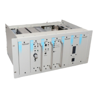
Details the electrical and physical characteristics of the T806 power supply.
Describes how the circuit reduces output voltage to maintain constant current when limit is exceeded.
Explains how thermal shutdown operates via transistor Q9 to protect switching elements.
Describes IC2's function in disconnecting the battery if voltage drops too low.
General information and precautions for servicing the T806 unit.
Covers lethal voltages, handling fragile components, ventilation, heat, and ESD.
Provides step-by-step instructions for disassembling the unit.
Covers procedures for replacing components on the PCB.
Recommends procedures for removing and fitting components without damaging the PCB.
Details two methods for removing components from Plated Through Hole (PTH) PCBs.
Outlines the process for replacing semiconductor devices, including torque specifications.
Lists necessary test equipment: isolating transformer, variac, ammeter, multimeter, oscilloscope.
A flowchart for diagnosing issues with the output voltage.
A flowchart for diagnosing faults related to the PWM control circuit.
A flowchart for diagnosing issues with the float charge output.
Details the importance of secure earthing connections for safety and noise suppression.
Describes how to use the T806 to float charge a 12V battery.
| Brand | Tait |
|---|---|
| Model | T806 |
| Category | Power Supply |
| Language | English |