Do you have a question about the TANDBERG SM6610 and is the answer not in the manual?
Defines the manual's coverage, purpose, and scope.
Explains the modulator's function in a typical system and its purpose.
Provides a concise overview of the modulator's key capabilities and specifications.
Details the standard and optional features enhancing modulator functionality and flexibility.
Lists the primary use cases for the modulator in DVB and non-DVB systems.
Highlights advanced features like Spectrum Sense and control options.
Offers a step-by-step walkthrough of the modulator's construction and controls.
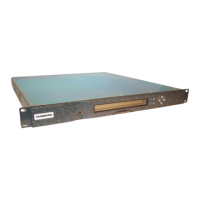
Describes the physical enclosure and rack-mounting capabilities of the modulator.
Details the front panel controls, LCD display, and LED indicators.
Identifies and describes the input/output connectors located on the rear panel.
Explains the function and availability of optional input modules for data streams.
Provides a checklist for initial setup and operation of the equipment.
Critical initial safety and installation information before proceeding with setup.
Detailed procedures for physical installation, including handling and rack mounting.
Instructions for securing the modulator using rack brackets and support shelves.
Guidelines for ensuring adequate airflow and preventing overheating during operation.
Safety precautions for routing and connecting cables to prevent hazards.
Details on power supply requirements, fuse specifications, and electrical earthing.
Steps for connecting various system components to the modulator.
Comprehensive guide to all signal inputs and outputs, including specifications.
Procedures for safely powering the modulator on and off, including warm-up periods.
Guide to controlling the modulator using terminal emulation software.
Step-by-step instructions for configuring terminal emulation software for connection.
Instructions for establishing remote control via Telnet over a network.
Explanation of how to move through the modulator's menu system and screens.
Details on using menu commands and understanding the hierarchy for operation.
Overview of the primary menu structure for configuring and testing the modulator.
Access to common settings for rapid modulator configuration.
Functions for viewing and managing alarm conditions and masks.
Options for managing, storing, and activating modulator configurations.
Access to system-level settings like identity, time, and network configuration.
Tools for viewing and resetting alarm, event, and temperature logs.
Access to diagnostic tests for verifying modulator functionality.
Procedures for validating, switching, and managing software versions.
Overview of controlling the modulator using the front panel interface.
Instructions on using front panel pushbuttons and screen symbols for menu navigation.
Explanation of the two primary operational modes: Monitor Only and Full Access.
Describes the limited access mode for viewing status and logs without making changes.
Details the mode allowing full control, editing, and configuration of the modulator.
Explains how to modify parameters within the front panel interface.
Method for changing individual configuration parameters directly.
Process for modifying and applying a set of configuration changes.
Practical guide demonstrating front panel IP address configuration.
A table listing all available configuration settings and their options.
Overview of the RS-232 remote control protocol and interface requirements.
Details on RS-232/485 and Ethernet interface specifications for remote control.
Explanation of the TLV message structure and protocol basics.
Outlines the configuration-based remote control concept for SM66XX models.
Provides a diagram illustrating the remote control workflow and message types.
Lists and describes commands that can be sent to the modulator via RS-232.
Command to activate a stored configuration on the modulator.
Command to download and activate a configuration file to the modulator.
Command to save the current configuration to a specified slot.
Lists and describes responses and status messages received from the modulator via RS-232.
Response containing specified configuration details from the modulator.
Response containing the modulator's currently active configuration.
Command to retrieve the current operational status of the modulator.
Command to save the modulator's current settings to a designated slot.
Overview of the RS-485 remote control protocol and interface requirements.
Details on RS-485 interface specifications and configuration for remote control.
Explanation of the TLV message structure and protocol basics for RS-485.
Outlines the configuration-based remote control concept for SM66XX models using RS-485.
Provides a diagram illustrating the RS-485 remote control workflow and message types.
Lists and describes commands for RS-485 remote control.
Command to activate a stored configuration via RS-485.
Command to download and activate a configuration file via RS-485.
Command to save the current configuration to a specified slot via RS-485.
Command to retrieve the current operational status via RS-485.
Command to save the modulator's current settings via RS-485.
Explains fundamental DVB-S and DVB-DSNG modulation and error correction principles.
Details BPSK and QPSK modulation schemes used in DVB-S.
Describes 8PSK and 16QAM modulation schemes for DVB-DSNG.
Explains FEC coding and interleaving techniques for error correction.
Provides an overview of the modulator's internal architecture and card functions.
Describes the functions of the Baseband card, including ASI interfaces and rate adaptation.
Details the functionality of IF and L-Band Output cards for signal processing.
Explains the role of the Host Controller Card in managing system functions.
Describes the optional input card for DVB ASI and SPI data streams.
Outlines regular checks for cooling fans and general cleaning procedures.
Identifies conditions that necessitate servicing and replacement part guidelines.
Lists symptoms indicating a need for professional maintenance or repair.
Step-by-step guide for operators to diagnose and resolve common equipment issues.
Information on interpreting boot display messages and self-test results.
Explains messages displayed after self-tests and recommended remedial actions.
Troubleshooting techniques for resolving high error rates in received signals.
Diagnostic steps for issues related to power supply and the front panel Power LED.
Troubleshooting guide for when the Power LED is not illuminated.
Procedures for diagnosing and resolving cooling fan failures and overheating.
Details on how alarms and failures are reported, including severity levels and groups.
Defines the six severity levels used to classify alarm conditions.
Lists alarms specific to the Host Controller Card and their severity.
Lists alarms originating from the Input Card and their severity.
Lists alarms specific to the Baseband Card and their severity.
Lists alarms originating from the IF Card and their severity.
Introduction to using FTP for file management on the modulator.
Steps for establishing an FTP connection to the modulator.
Description of the directory containing the modulator's software files.
Details the directory storing firmware files for FPGA devices.
Information about the directory containing system and alarm log files.
Explains the directory holding stored configurations and system information files.
Guide on how to download files from the modulator using a web browser or FTP client.
Explains the role of licence keys in enabling modulator features and software options.
Instructions on how to purchase and acquire licence keys from sales representatives.
Procedures for entering a single licence key to enable features.
Method for downloading and entering a licence key file via FTP.
Process for entering multiple licence keys, potentially from a single file.
| Output Frequency Range | 47 - 862 MHz |
|---|---|
| Output Impedance | 75 Ω |
| Power Supply | 100-240 VAC, 50/60 Hz |
| MER | ≥40 dB |
| Constellations | 16QAM, 32QAM, 64QAM, 128QAM, 256QAM |
| Bandwidth | 8 MHz |
| Return Loss | 14 dB |
| Operating Temperature | 0°C to +45°C |