11
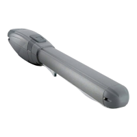
ZIP Series
ENGLISH
• do not touch the motor unless you are sure it is cold
• only operate the door when it is completely visible
• keep out of the door’s range of action if it is moving: wait until it
has stopped
• do not let children or animals play near the door
• do not let children, or incapable people, use the remote control
or other operating devices
• carry out routine maintenance
• in the case of a failure, turn the electricity off and operate the
door manually only if it is possible and safe to do so. Refrain
from touching the door and call an authorised technician.
WIND PRESSURE
Note: Falls der Getriebemotor an einem Tor mit durchgehend aus-
gefachtem Drehügel installiert wird, muss die Motorkraft an Orten
mit ständigem Wind so eingestellt sein, dass sie auf jeden Fall
kleiner als 15 Kg Höchstschub ist (gemessen am Ende der an-
schlagenden Kante, wie vorgesehen von den Normen prEN 13241
und prEN 12635); falls die Kraft so eingestellt wird, dass sie diese
Sicherheitsgrenze überschreitet, übernimmt die Firma TAU keiner-
lei Haftung für die eventuelle Gefährdung Personen.
MAINTENANCE
The gearmotors in the ZIP serie need very little maintenance. How-
ever, to ensure it always works properly, the gate has to be in good
condition.
Attention: no one, except the person who services the equipment
(who must be a specialised technician), should be able to com-
mand the automatism during servicing. Consequently, it is advis-
able to turn the electricity off at the mains also to avoid possible
electric shocks. If the electricity has to be on for certain checks,
check or disable all command devices (remote controls, push but-
ton panels, etc.) except for the device being used by the mainte-
nance person.
Automation system
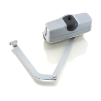
• Keep oiled the jointed arm’s pin, the boss that works coupled
to the motor output shaft and all parts subject to wear due to
friction.
• Check how the safety devices are working (pneumatic edge,
torque limiter, etc.).
Routine maintenance
• Each of the following operations must be carried out when nec-
essary and always every 6 months for domestic use (approx.
3000 work cycles) and every 2 months for intensive use such
as blocks of ats (always 3000 work cycles).
Extraordinary maintenance or breaks
• If there are any complex jobs that need be done on electrome-
chanical parts, it is advisable to remove the actuator so that
it can be repaired in the workshop by the manufacturer or its
authorised technicians.
ANNEX (g. 11 - g. 12)
SAFETY DISTANCES FOR AUTOMATIC GATES
• The distance A (g.11) between the jamb and the upright next
to the gate must remain constant when the gate rotates. If this
varies, the maximum distance must be 25 mm up the whole
height of the gate; if this is not the case, ll in the extra space
for the total height of the gate up to a maximum of 2.5 m.
• The distance B (g.11) between the oor and the leaf must be
minimum 50 mm, if distance B varies due to sloping ground,
the tter must take steps to reduce the danger of people or
objects getting trapped.
• In a two-leaf gate, the distance C (g.12) between the two
closed leafs must be at least 2,5 cm; this space can be covered
by installing a pneumatic edge on the side of the leaf or tting
a deformable exible element in the free space. If this space is
smaller or absent, the two leafs must be closed in sequence so
as to leave a clearance D (g.12) of 50 cm.
SAFE INSTALLATION HINTS
Man present operation: an emergency stop device and a ashing
light is sufcient
Automatic or semiautomatic operation: install a ashing light
and adjust motor torque as described below; if this is not possible,
t a pneumatic edge.
• t one photocell at both gate’s sides thus limiting the gate’s
operating range. If the leafs overlap due to a stop prole they
must be put out of phase (distance D g. 12).
For all operation types: If the leaf stops during the opening phase
at a distance (see gure on the previous page) of less than 40 cm
with respect to a xed obstacle (wall, pillar, etc.), a pneumatic edge
must be tted to the leaf or the xed part as follows:
1 - if the obstacle is higher than it is wide apply the edge (for the
whole length of the obstacle) at a height of between 40 and 60
cm from the ground;
2 - if the obstacle is wider than it is high and is lower than 60cm
apply the edge 5 cm from the upper edge of the obstacle.
CHARACTERISTICS, ADJUSTMENT AND INSTALLA-
TION OF SAFETY DEVICES
Photocells :
• These are tted at a height varying from 40 and 60 cm from the
ground at a max. distance of 10 cm calculated from the edge of
the open leaf and from the edge of the closed gate.
Sensitive safety edge
• In the simplest cases there must be Normally Closed (NC) con-
tacts;
• Minimum deformation must be at least 1 cm greater than the
stopping distance of the gate from when the device cut in
Torque limiting device
• This must be adjusted so that the gate stops in the presence
of a mechanical resistance of 150 N (about 15 Kg) measured
on its edge as long as the kinetic force of the leaf is not greater
than 10 J.
ZIP INSTALLATION (g. 13)
1 Gearmotor ZIP
2 Electric locks
3 Pillars
4 Control unit
5 Aerial and ashing light
6 Photocells
7 Key selector
8 Main switch
ZIP12 INSTALLATION (g. 14)
1 Gearmotor ZIP
2 Electric locks
3 Pillars
4 Control unit
5 Aerial and ashing light
6 Photocells
7 Key selector
8 Main switch
 Loading...