Do you have a question about the TE 1410 and is the answer not in the manual?
Explains the TE Systems Model 1410G RF amplifier subsystem and its dual function.
Lists performance parameters like frequency, input/output power, class of operation, and physical dimensions.
Details how to identify the model and serial numbers on the front and rear panels.
Describes available hardware options, factory modifications, and accessory availability.
Outlines the product warranty terms, specific component coverage, and limitations.
Lists the accessories included with the RF amplifier, such as manuals and connectors.
Instructions for visually checking the RF amplifier for damage upon receipt.
Describes how to connect the amplifier between a transceiver and antenna using coaxial cables.
Details rear panel connectors for DC voltage, RF input/output, and accessory socket.
Discusses mounting the amplifier, including using rubber feet or optional brackets.
Specifies the DC voltage and current needs for the amplifier, recommending a suitable supply.
Details operating temperature range and potential damage from extreme conditions.
Explains the internal thermostat and environmental sealing of the unit.
Overview of the Model 1410G RF amplifier and its dual transmit/receive functions.
Describes the basic operation of amplifying transmit signals and low-noise receive signals.
Procedure for turning on the RF power amplifier and verifying its status.
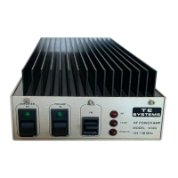
Describes the function of front panel switches and status lights.
Procedure for activating the low-noise receive preamplifier and its status indication.
Explains the function of the mode switch (FM vs. CW-SSB) for T/R delay.
Details the capabilities of remote control operation for the amplifier.
Specifies the pin assignments for the remote accessory socket and their functions.
Explains how to configure remote control functions and hard-keying.
Discusses heat management and thermostat function during operation for preventing damage.
Explains how the RF signal is amplified by the power amplifier stages.
Describes the function and protection of the low-noise receive preamplifier.
Details the transmit/receive switching mechanism using relays.
Illustrates the overall system architecture and signal flow.
Presents the detailed electronic circuit schematic for the Model 1410G.
Enumerates the components used in the amplifier's construction.
Outlines performance tests and adjustment procedures for the unit.
Procedure for adjusting the RF power amplifier's performance, including input VSWR.
Details how to check output power and VSWR of the amplifier.
Describes the tuning procedures for input VSWR and output power.
Procedure for aligning the low-noise receive preamplifier for optimal performance.