Do you have a question about the Team Losi BK2 and is the answer not in the manual?
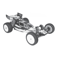
Specific measurements of the assembled RC buggy.
Explains common symbols and notes used throughout the manual.
Describes how the manual is structured and organized for assembly.
Crucial safety guidelines for assembly and handling of the RC car.
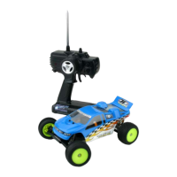
Information and considerations for the radio and electrical components.
Guide to identifying and understanding the various hardware parts.
Details on motor types and recommended initial gearing ratios.
Instructions for assembling the servo saver mechanism.
Details on installing ball studs into various components.
Steps for connecting the servo link to the steering assembly.
Instructions for installing the steering components.
Guide to installing threaded inserts into the chassis.
Steps for attaching the front kickplate to the chassis.
Instructions for mounting the front bulkhead.
Steps for assembling the front shock tower.
Instructions for installing the assembled front shock tower.
Detailed steps for assembling the front spindle components.
Instructions for attaching the spindle to its carrier.
How to attach ball studs to the front spindle assembly.
Steps for assembling the front suspension arms.
Instructions for installing the front suspension arms.
How to assemble the tierod and camber link components.
Steps for installing the camber links.
Assembly instructions for the steering tierod.
Steps for installing the steering tierod assembly.
Instructions for assembling the CVD dogbone.
Steps for assembling the rear hub components.
Instructions for installing the rear hub assemblies.
Steps for installing rear arms and suspension components.
How to assemble the rear shock tower.
Instructions for installing the rear shock tower.
Assembly of rear camber tierod components.
Steps for installing the rear camber links.
Instructions for assembling the differential nut.
Steps to attach the differential nut to the outdrive.
How to attach the drive ring to the male outdrive.
Instructions for installing the differential gear.
Steps to attach the differential gear to the male outdrive.
Instructions for inserting bearings into the female outdrive.
Steps for assembling the differential adjusting screw.
How to attach the differential ring to the female outdrive.
Instructions for assembling the complete differential.
Instructions for installing bearings into the left gearbox half.
Steps for attaching the motor plate to the right gearbox half.
Instructions for assembling the right gearbox half.
Steps for assembling the main gearbox housing.
Instructions for assembling the slipper clutch mechanism.
Instructions for installing the assembled gearbox onto the chassis.
Steps for installing the motor guard.
Instructions for assembling the shock absorber cartridges.
Steps for installing the shock shafts into the cartridges.
Instructions for installing the shock ends onto the shafts.
Steps for assembling the shock pistons.
Instructions for filling the shocks with oil and bleeding air.
Information on shock adjustment nut assembly.
Steps for installing the assembled shocks onto the car.
Instructions for installing the rear shocks.
Steps for installing the front shocks.
Instructions for mounting and installing the tires onto the wheels.
Instructions for installing the motor and gear cover.
Steps for installing the servo arm.
Instructions for installing the servo mounting posts.
Steps for mounting the servo onto the chassis.
Instructions for creating the servo link.
Steps for installing the servo link.
Instructions for installing the rear body mounts.
Steps for installing battery foam and strap.
Instructions for installing the receiver.
Steps for installing the speed control.
Guide to painting the RC car's body and wing.
Instructions for trimming and installing the car's body.
Steps for installing the rear wing.
Guide to adjusting the differential for optimal performance.
Instructions for adjusting the slipper clutch.
Ensures all suspension parts move freely without binding.
Guidance on setting the car's ride height.
How to adjust the tire camber for better handling.
Instructions for setting the front tire toe-in.
Guidelines for charging the battery pack.
How to adjust the speed control settings.
Adjusting transmitter steering trim for straight driving.
Detailed explanation and tips for differential adjustment.
Further advice on adjusting the slipper clutch.
Discusses key tuning adjustments like ball studs and anti-squat.
Explanation of how ride height affects car handling.
Guidance on setting rear hub camber location for handling.
How rear camber link length impacts car handling.
Discussion on front carrier camber location and its effects.
Tips on using washers for front camber link ball studs.
Explains how front camber link length affects car handling.
How shock location impacts steering and handling.
Adjusting rear shock location for optimal performance.
Guide to adjusting rear anti-squat for better traction.
Adjusting rear hub spacing for different track conditions.
Tips on battery placement for traction and balance.
Explanation of Variable Length Arms (VLA) for tuning.