INSTALLATION
Place the units on a laboratory bench. Depending on the sol-
vent you are going to use, the Extraction Unit might be locat-
ed in a fume cupboard separated from the Service Unit.
As an alternative there is a connection on the rear of the Ex-
traction Unit which can be connected via fiexibie tubing to a
ventilation fan. The Extraction Unit must be placed close to a
cold water tap and drainage.
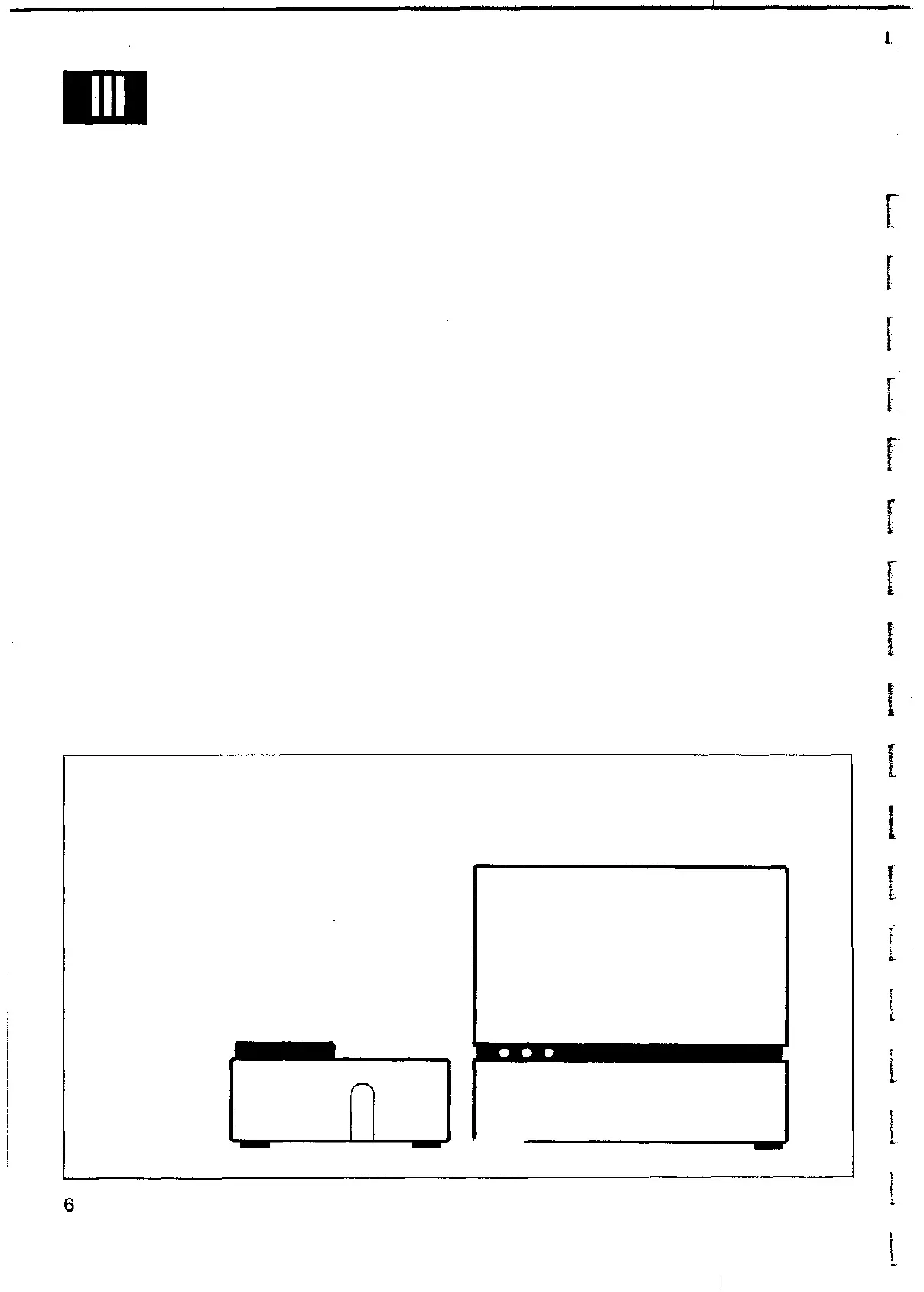
111:1. CONNECTION
Connect the PVC-tubing (0 8/11 mm) for cold water according
tofig. B.
Connect the insulated rubber tubing for hot water according
to f ig. B. Make sure that the rubber seals are on place. (Fig. C)
It is enough to fasten the connection by hand.
The Service Unit must be placed close to a wall socket. Never
connect it without water in the tank. Connect the hot water
tubing from the Extraction Unit and the PVC-tubing for air.
Seefig. B.
If necessary the Extraction Unit can be placed further away
from the Service Unit (standard length of the hot water tubing
is 3 m). For this purpose the 1000-1460 extension kit should
be used.
If you are going to connect an additional Extraction Unit use
the 1000-1461 assembly kit.
r
r
Fig. B
1. Cold water inlet for con-
densers (water flow 1—2 1/
min.)
2. Water outlet from conden-
sers
Hot water connections: 7 con-
nected to 3 and 8 connected
to4
Air tubing connection: 6 con-
nected to 5
9. Electrical cable
1 2
6 o
70
8 O
O9
3
O
4
O O
5
o
 Loading...