ELECTRICAL CONNECTIONS BETWEEN INDOOR AND
OUTDOOR UNITS
1. To connect the indoor unit to the outdoor unit
use the following electrical cables, protected for
outdoor use:
Multiple wire cable (220-240V, 50Hz).
5 wires x 1.5 mm
2 wires x 0.5 mm - for low voltage
(supplied with the unit).
Multiple wire cable (220-240V, 50Hz)
4 wires x 1.5 mm
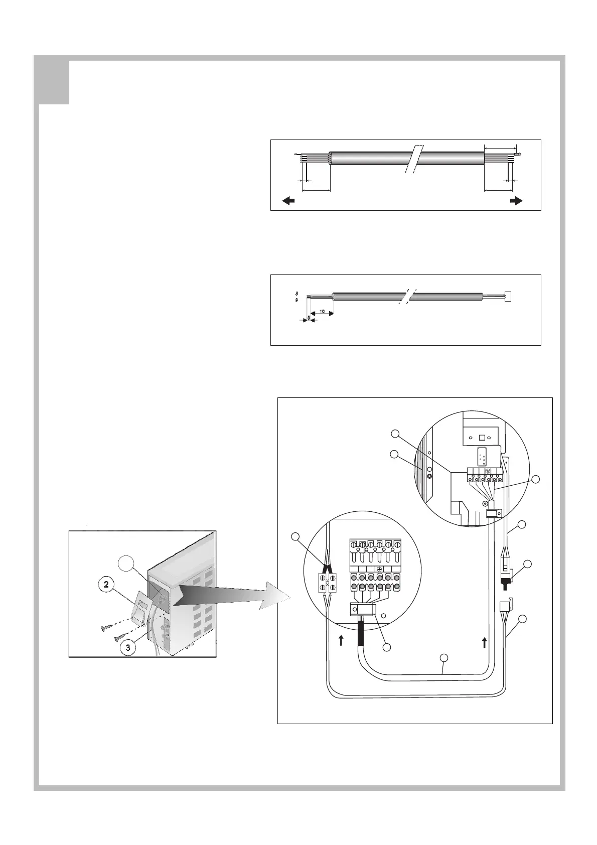
2. Prepare the multiple wire(7)cable ends for
connection as shown in fig.18.
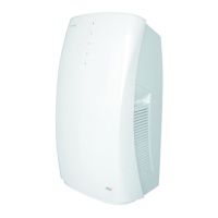
3. Connect the cable ends to the terminals of
the indoor and outdoor units, as shown in
fig.20.
4. Shape a loop and connect the yellow/green
ground wire (2) to ground terminal screw of
the indoor unit, as shown in fig.20.
For multi split and cooling only units skip
steps 5, 6, 7 and 9.
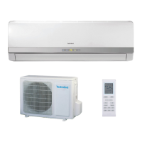
5. Prepare the twin wire cable end for connection
as shown in fig.19.
6. Disconnect the resistor (5) from the indoor unit
twin wire cable (3) and connect the win wire
cable (6) connector instead.
7. connect the other end of the twin wire cable
(6) to the outdoor unit twin wire terminal (9).
8. Secure the multiple wire power cable with the
cable clamps.
9. Fasten the twin wire cable to the power cable
with cable ties.
Cooling and heating model:
Cooling only models:
NOTE:
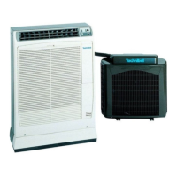
Fig.17
1.Terminal 2.Cover 3.Cable tie
NOTES:
1. The wire color code can be selected by the
installer.
2. Wires leading to outdoor unit twin wire
terminal (9). must be in a separate twin wire
cable, otherwise the electronic controls will
be subjected to operational malfunctions.
3. For cooling only model, terminal number 6
should not be connected.
MULTIPLE WIRE POWER CABLE
Fig.18 A.OUTDOOR B.INDOOR
TWIN-WIRE LOW VOLTAGE CABLE
6
BA
Fig18
Fig19
Fig 17
2
2
2
1
Fig.20
1.Indoor unit terminal
2.Ground wire
3.Indoor twin wire cable
4.Indoor coil
5.Resistor
6.Twin wire calbe
7.Multiple wire calbe
8.Cable clamp
9.Outdoor twin wire terminal
A.OUTDOOR B.INDOOR
100
40
8
8
250
Fig20
8
9
4
5
2
A
1
4
4
5
6
5
3
6
7
B
2
21
COOL
HEAT
RESET
MODE
61
98