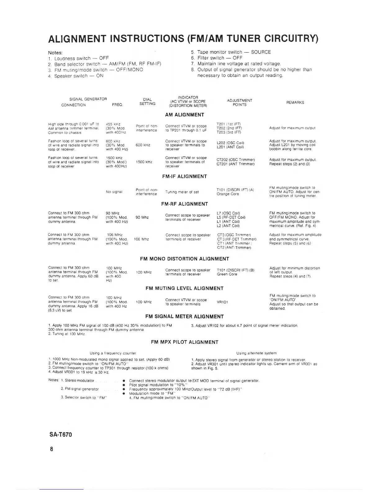
ALIGNMENT
INSTRUCTIONS
{FM/AM
TUf{ER
CIRCUITRY)
Notes:
5.
Tape
monitor switch
-
SOURCE
1. Louciness
sw'tch
-
OFF
6.
Filter
switch
-
OFF
2.
Band setector
switch
*
AMIFM
(FM,
RF
FM-IF) 7. Maintain line vollage
at
raled voltage.
3.
FM
muringlmode
switch
-
OFF/MONO
B. Outpui of signal
generator
should be
no higher
than
4.
Speaker
switch
-
ON
necessary
to obtain an oulput
reading.
SIGNAL GENERATOR
DIAL
INDICATOR
ccNNEcrQN
FHE0.
srn-rr.rc
,$18r5J#"fi
i,3:8,
ooigilys"t
REMAFKS
AM ALIGNilIENT
Hlgn sroe
tnrolgn
'l
00: uF
'o
das
rPz
o^,^-
^t
.^^- .^,\^o^,\n\J\,
^,
c.n^6
I?O1 ,15r
;FTi
Ar,i
a.renna
:rlmmer
,e'm,1ar
ll9^",XT_
nll.i"","nl" ;"";pil,
;;;;;r;
d;;
l?0l
,2nc
rm
Adrust
ror
na4mLm
cursJr
Common
to
cnassrs.
wrln
iCOHz
1203
{3rd
iFn
Fashron
looo
o{
several
lurns
6CO
kl^{t
Csnnect
VTVM
or scope
Adjusl ior
maximum
oulpul.
*;:::#"r""Jl'-
slsnai
rnlo
fl;'i$1,
600 kHz
["'i::l''
rsr'nrnars
'b
331ixff #]ii
f3$:l:t:;r%fl,"J':3,:""
Fashion loop
ol several
turns
1500 kHz
connecl
vrvM or
scote
cr202
(osc rrimmeO
Adjust
tor rnaximurn
ourpur.
of
wir6 and
radiale
signal
lnlo
(30%
Mod.)
1500 kHz to
speaker
termrnals o1
ct20t
(ANT
Trimmeo Repear
$teps
(2)
and
(3)
loop ol receiver
wilh 400H2)
receiv€r
FM.IF ALIGNTdENT
Pc ni
or
non'
run,ns
nete,
or ser
119:i9F::',
'-"o'
[I,r^i';1,fi*^'.;;'ii:,':".'
No
ilgna'
nierrerence
lunlnq
nglel
ol sel
v'o, y!
uv's
:re
gos,l,on
ci
runlng
merer
FM'RF ALIGI.TMENT
Connect to FM
300
ohm
90
MHr
L7 {OSC Corl
Fhl muringlmode
switch
to
anlenna
lerminai ihrough FM
{100%
Mog. 90 Mhz
connecl
scooe
lo
spgai(er
du,omy antenna
w*h
400 Hz)
refminars
of
receiver
i?
ilii5:,i-'
3li;lY"i""rir?,i?:'jJ1,
t2
{ANT
ColU
rnetrical curve.
(Fet.
Fig- 4)
Connecl lo FM
300
ohm 106 MHz
Connect
scope lo speaker CT3 {OSC
Tilnmer) Adjusl
ior maximum
amplilude
anlenna
lermrnal lhrough
Flv'l
(100%
Mod.
106
Mhz lerminals ol receiver
cT3iRF.DET Tilmmer)
and
symmetrical
curve.
durnmy
antenna wrlh
400
Hzi CT
I
iANT
Tflmmer
I
Repear
sleps {5) and
{6)
CTA
{ANT
lrimmer)
FM MONO DISTORTION
ALIGNMENT
:;il::
L*Y,"1T,?X?,
,"
i,ofou"il"d
100 MHz
conn€cr scope
1o
speaker r10llDrscRr
rm
iB)
liHiJi:lJi"'"m
dislorlron
dummy
antenna, Appty
80 da
with
{00
l€rminals ol f$ceiv6r
Greel cofe
i"pr"r
,r"p.
i4}
and
(7).
lo
set. Hz)
FM MUTING
LEVEL ALIGNMENT
Connect to FM
300
ohm
10o MHz
M
mulinglmode
swilch to
anlenna
rermrnat
rhroush
FM
{100%
Mod.
100 MHz
connecr
vryM
or scope
vR101
^?X|ij$:i*,pul
can be
dummy
antenna.
Ap0ty 16
dg with 400 Hz
lo speaksr iermioals
(6.3
uV) to
set.
'-
oblained'
FM
SIGNAL METER
ALIGNMENT
1.
Appty 100
MHz
FM
signal
of
100
dB
(400
ila
30%
modulalion)
to FM
3. Adjust VR102 for about
4.7
point
ot
signal
merer indicarion.
300 ohm anlenna
terminal through FM
dummy antenna.
2. Tuning
at 100
MHr.
FM MPX
PILOT
ALIGNMENT
Usang a
iraqueflcy
ccunter
Using
alt€,(nal€ syslem
11000MHzNon'moduialedmonosignal
aopliedioset.{Apply60dB)
1.Applyslereqsignat
lromgeneralororstereoslalionlcreceiver.
2, FM
muling/.node
se/ilch
to
'ON/FN.l
AUTO"
2.Adj!il VH301
u;tii steraoindicalor
lighls up. Cemenr
arm sf
VR301
as
3. Connecl
frequency
counter to IP301 lhrough resislor
{.l00
k
ohms} sfrown in Fig.
5.
a.
Adjrrsl
VR301
to
tg
kHz
r 30
Hz.
Noles:
1.
Steroo
modulalor
. a
Conftecl
stereo
modulator oulpul
td
EXT MOD terminal
ol srgnal
gensrator.
a Pilot
signal
modulaiion
to
"10Yo"
2,
FM
srgnal
gensralor
r
Frequency
approximalely
100
MHz/Output level
to
"72
dB
(lHF)"
.
Modulalion
mods io
"FM"
3. S€leclor
swrlch
to
"FM"
4. FM muting/mode
switch ro
"ON/FM
AUIO"
sA.T870
I