In DYN mode the waveform heights of each connected channel (cylinder) and the relative positions of
their crests & troughs are displayed side by side for direct comparison.
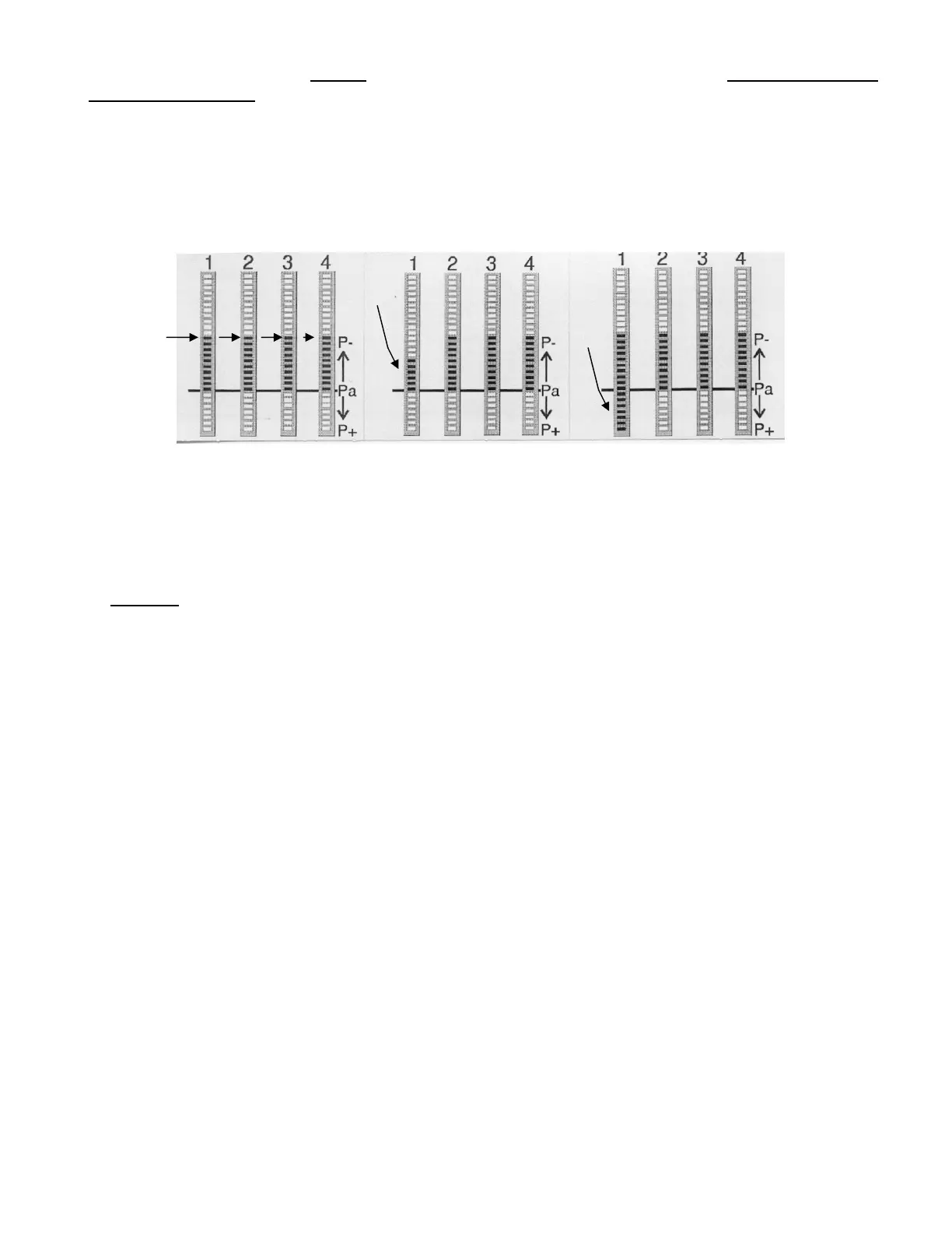
When all carburettors have been correctly synchronized and everything works normally, the bands
should all have the same height and position. (See illustration below left and comment** below).
** Note that this statement is not precisely true of certain engines for example that of the Honda
VFR800 motorcycle and certain Mercury, Mariner & Yamaha 4-stroke outboard motors on which
certain cylinders have slightly different “AVE” intake vacuum setting values by design.
☺
100% NORMAL EXHAUST VALVE INTAKE VALVE
The VacuumMate has an auto-ranging feature in DYN mode. The range is automatically adjusted to
achieve optimal resolution for the comparison of the connected channels. The channel with the
highest waveform crest governs the auto-ranging adjustment. The bases of the displayed columns of
light for engines without defective seals should normally be almost exactly opposite the “Pa” mark (Pa
= Atmospheric pressure) on the right hand side of the LED displays (see above left). Other than the
Pa mark there are no scale markings for the DYN mode as the purpose is not to measure but rather
to compare
the connected channels. A light column extending downwards into the P+ zone (below
the Pa level) means POSITIVE pressure (higher than atmospheric), upwards into the P- zone means
vacuum.
Some abnormal display patterns are shown above, centre and right. The nature of the waveform
anomaly reveals the nature of the engine sealing defect because various different defects give rise to
different patterns of waveform anomaly. The most common anomalous wave-forms are shown on
the next page.
EXAMPLE 1 :
EXHAUST VALVE NOT CLOSING
When one of the exhaust valves is not closing completely, a part of the exhaust gas will be “sucked
back” into the combustion chamber during the intake stroke. This is evident from the “DYN” mode
LED column displayed for that cylinder, whose highest point (crest of the vacuum wave-form) will be
lower than on the other (normal) channels.
FALSE AIR INTAKE
'False air’ is air which is sucked into the cylinder after the throttle valve. For example in case of a leak
in the intake manifold. The display in DYN mode looks very similar to that of a leaking exhaust valve.
The highest point of the LED column displayed for that cylinder will also be lower than on the other
channels.
A typical anomalous wave-form for these defects is illustrated on the next page.
8
 Loading...