IST-2282.IF01.01 Istruzione / User’s Manual / Manuel d’utilisation Pag.9/9
TECNOCONTROL S.r.l. Via Miglioli 47 SEGRATE ( MI ) ITALY
Tabella 1 / Table 1 / Tableau 1
Cable Size
Section des câbles
[Singolo Conduttore]
Cable Resistance
[Single wire]
Résistance câbles
[par Conducteur]
La max distanza, cui può essere installato
ogni rivelatore dall'alimentatore a 12Vcc
The maximum distance to install each detec-
tor from the 12Vdc power Supply
Distance maxi d’installation du détecteur
sous 12Vcc
La max distanza, cui può essere installato
ogni rivelatore dall'alimentatore a 24Vcc
The maximum distance to install each detec-
tor from the 24Vdc power Supply
Distance maxi d’installation du détecteur
sous 24Vcc
Tabella 2 / Table 2 / Tableau 2
OFF
ON
Tabella 3 / Table 3 / Tableau 3
1 2 3 4 5 6 7
Modello
Model
Modèle
Standard Range
Champ de mesure
Gas bottle
Bouteille de gaz titré
Flowmeter
Débitmètre
(TP1/TP2)
mV
Output
Sortie
indication
Indication
2000 ppm
0.3÷0.5 l/min
12 mA
1000 ppm
1000 ppm
200 20 mA 1000 ppm
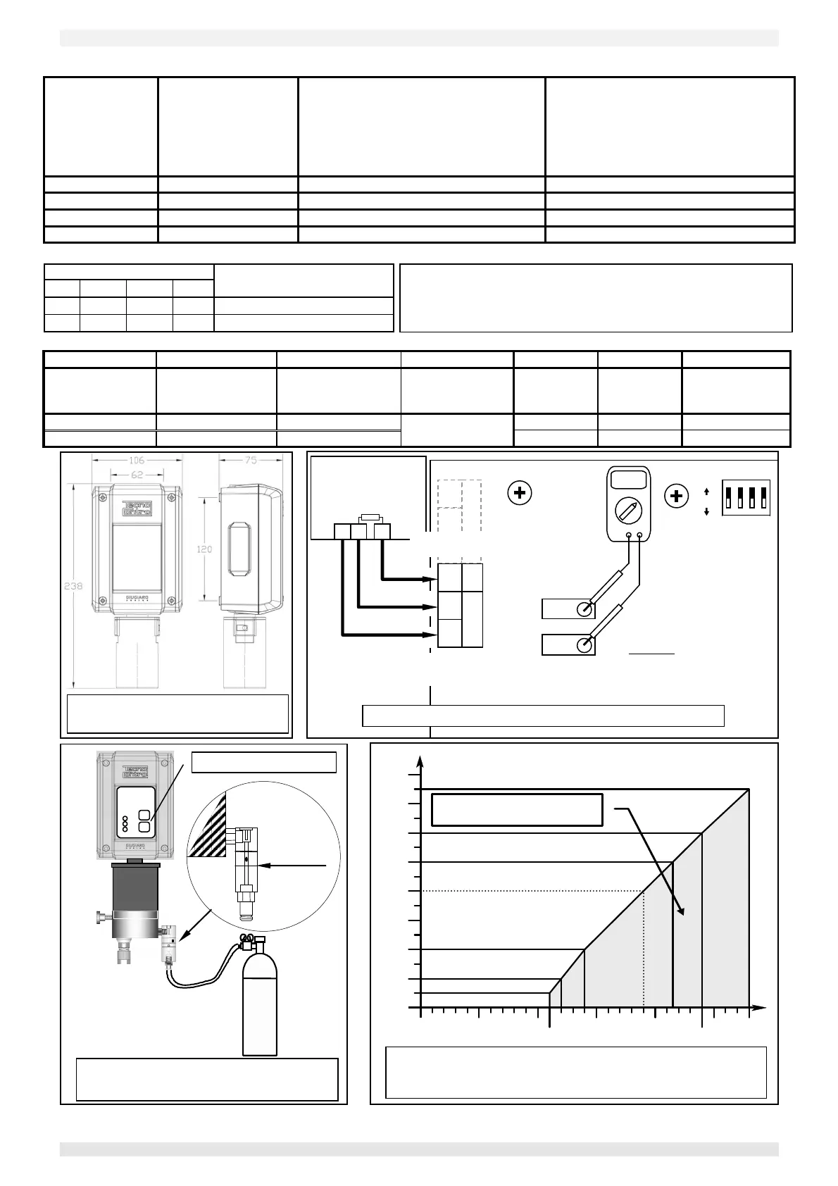
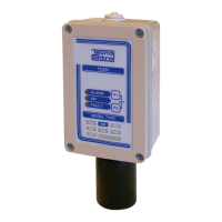
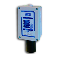
Fig. 1 –
Dimensioni /
1
2
3
4
Fig. 2 -
/ Wiring diagram / Schéma
TP2
TP1
Gas Central Unit
Centrale de détection
RL
Output Test
Sortie Test
40÷200mV
Alimentazione / Power Supply / Alimentation
4÷20 mA Output / Sortie en 4÷20 mA
Fig. 3 - Tester di calibrazione
/ Calibration Tester / Kit de Calibration
0,5 L/min
F1
F2
TC014
/ Power Supply / Alimentation
/ Load resistor / Resistance de charge
Ohm
Fig.4 - Alimentazione / Resistenza di Carico 4÷20mA
Power supply / Load resistance diagram 4÷20mA
Alimentation / Résistance de charge 4÷20mA
Area di funzionamento
Allowable oparating region
Il Dip-Switch va posizionato prima d’alimentare l’apparecchio.
Dip-Switch should be set with instrument powered off.
Les Dip-Switch doivent être paramétrés avant d'alimenter le détecteur