A LOOK AT SERVICE SAFETY
Installation and Replacement Information
97
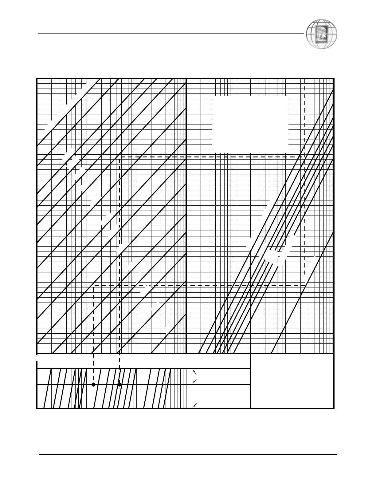
Figure 5-6.
Refrigerant line pressure drops for HFC-134a refrigerant (reprinted by permission of DuPont
Fluorochemicals).
0.2
0.3
0.4
0.5
0.6
0.8
1
2
3
4
6
8
10
20
30
40
0.1
0.2
0.4
0.6
1
2
4
6
10
20
30
40
60
100
0.1
0.2
0.3
0.4
0.6
0.8
1
2
3
6
8
10
20
30
40
60
80
100
At 80°F Condenser
At 100°F Condenser
At 120°F Condenser
6
1
/
8
"
O
.
D
.
T
y
p
e
L
C
o
p
p
e
r
T
u
b
i
n
g
-
6
0
°
F
E
v
a
p
o
r
a
to
r
T
e
m
p
e
r
a
tu
r
e
-
4
0
°
F
-
2
0
°
F
2
0
°
F
4
0
°
F
D
is
c
h
a
r
g
e
L
in
e
s
L
iq
u
id
L
in
e
s
0
°
F
5
1
/
8
"
4
1
/
8
"
3
5
/
8
"
3
1
/
8
"
2
5
/
8
"
2
1
/
8
"
1
5
/
8
"
1
3
/
8
"
1
1
/
8
"
7
/
8
"
3
/
4
"
5
/
8
"
1
/
2
"
3
/
8
"
Pressure Drop In Psi Per 100 Ft.
Tons of Refrigeration
EXAMPLE:
25 Tons at -40°F Evap. and 100°F Cond.
2
5
/8
" Suction Line
Pressure Drop = 5.5 p.s.i./100 ft.
1
1
/8
" Liquid Line
Pressure Drop = 1.6 p.s.i./100 ft.
NOTE: Pressure drops do not
allow for pulsating flow.
If flow is pulsating, use
next larger pipe size.
Liquid line and discharge
lines determined at 0°F
evap. and 80°F cond.
Other conditions do not
appreciably change
result. Vapor at evap.
outlet assumed to be at 65°F.
 Loading...