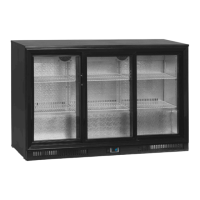
82
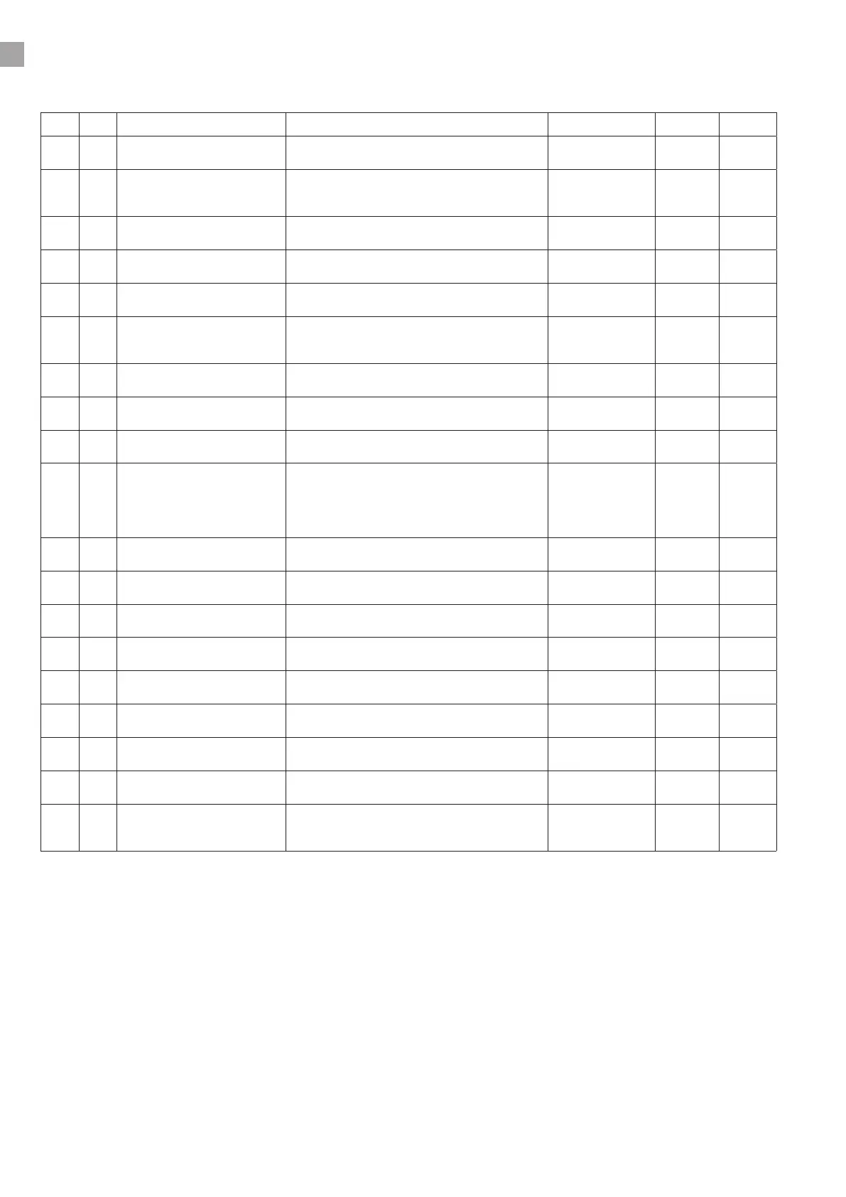
DT-01 PARAMETER LIST
No. Description Range Default Remarks
1 SP Set point Cut-out temperature "-55~99°C /
-67~99 °F"
4
2 dF Dierential Intervention dierential for set point. When the
temperature ≥SP+dF, compressor Cut IN , when
the temperature ≤SP, compressor Cut OUT.
"0.1~25°C /
1~45°F"
3
3 LL Minimum set point Set the minimum value for the set point. "-55°C~SP /
-67°F~SP"
0
4 UL Maximum set point Set the maximum value for set point. "SP~99°C /
SP~99°F"
8
5 CA Probe calibration Allow to adjust possible oset "-10~10°C /
-17~17 °F"
3,5
6 d1 Outputs activation delay at
start up
This function is enabled at the initial start up of
the instrument and inhibits any output activation
for the period of time set in the parameter.
0~99min 0
7 d2 Anti-short cycle delay Minimum interval between the compressor stop
and the following restart.
0~50min 5
8 Cy Compressor ON time with
faulty probe
Time during which the compressor is active in
case of faulty thermostat probe.
0~99min 20
9 Cn Compressor OFF time with
faulty probe
Time during which the compressor is OFF in case
of faulty thermostat probe.
0~99min 20
10 CF Measurement unit °C =Celsius; °F =Fahrenheit. WARNING: When
the measurement unit is changed the set point
SP and the values of the parameters dF. LL. UL.
AH. AL etc have to be checked and modied if
necessary.
°C / °F °C
11 rE Resolution Only for °C, dE= decimal between -9.9 and
9.9°C; in= integer
dE / in dE
12 d3 Display delay when the temperature increases, the display is
updated of 1 °C/1°F after this time.
0~15min 5
13 d4 Interval between defrost cycles Determine the time interval between the begin-
ning of two defrost cycles.
0~99hours 4
14 d5 Maximum length for defrost Set the maximum length for defrost,with 0 no
defrost
0~99min 25
15 dt Display during defrost rt= real temperature; it= start defrost tempera-
ture;SP= set point SP; dF= label dF.
rt / it / SP / dF it
16 AH Maximum temperature alarm When this temperature is reached, the alarm is
enabled after the “A1” delay time.
"AL~99°C /
AL~99 °F"
15
17 AL Minimum temperature alarm When this temperature is reached, the alarm is
enabled after the “A1” delay time.
"-55°C~AH /
-67°F~AH"
-2
18 A1 Temperature alarm delay Time interval between the detection of an alarm
condition and alarm signalling.
0~99min 10
19 A2 Exclusion of temperature alarm
at startup
Time interval between the detection of the tem-
perature alarm condition after instrument power
on and alarm signalling.
0~99min 99
 Loading...