3. Locate the Power Supply Circuit Assembly, Part No. 53157. (Attached to the rear panel.)
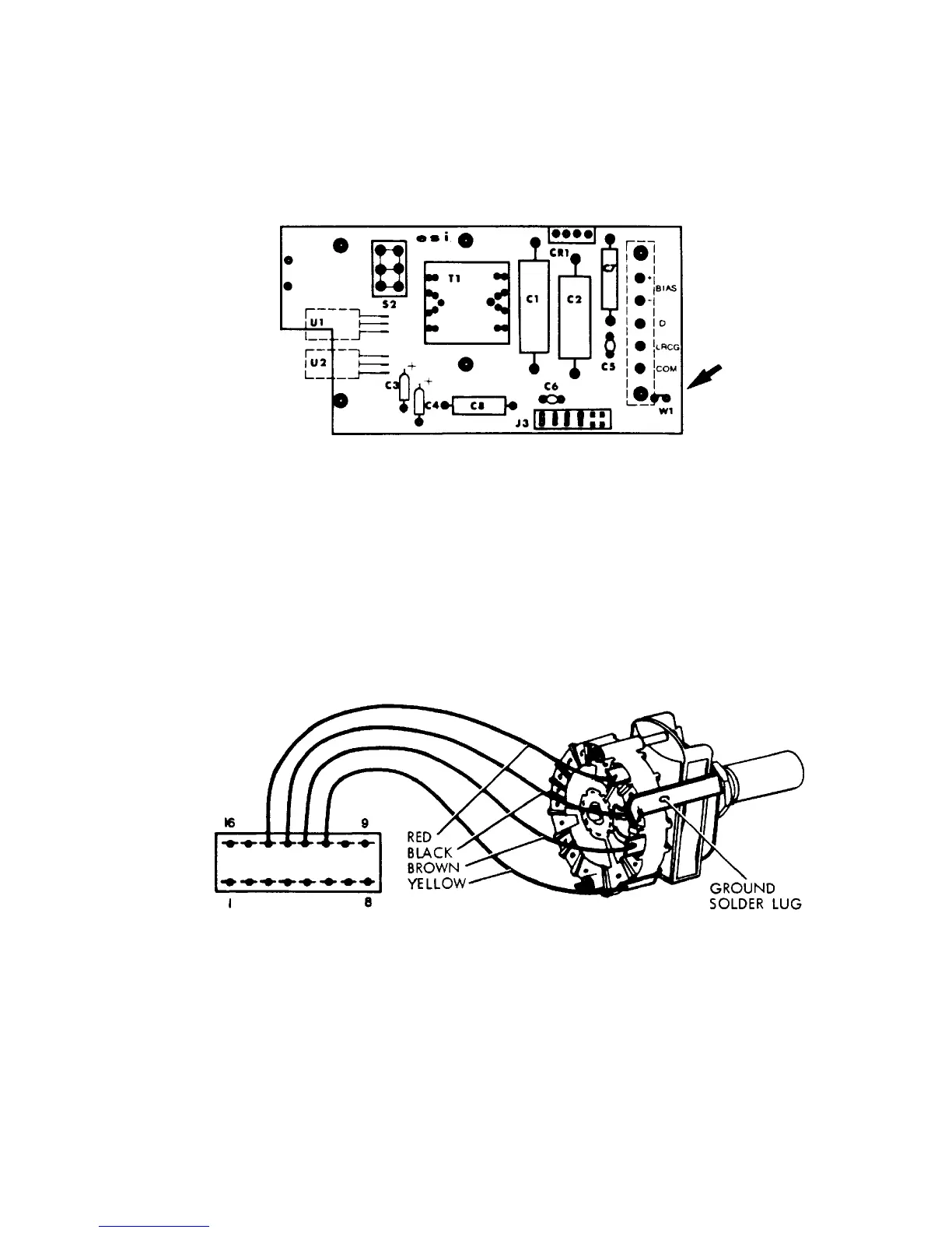
4. Remove jumper wire W1 from this assembly (see Figure 2-10).
Figure 2-10. Power Supply Circuit Assembly
5. Locate the Range Switch on the front panel.
6. Unsolder and isolate the ground solder lug from the Range Switch terminal and black
wire, making sure that the black wire remains attached to the Range Switch terminal (see
Figure 2-11).
7. Replace instrument cover.
2-24
Figure 2-11